
Contents: Removal ⇓ Disassembly (75 A) ⇓ Check (75 A) ⇓ Checking the rectifier unit ⇓ Replacing brushes ⇓ Disassembly (90 A) ⇓ Check (90 A) ⇓ Checking the rectifier unit ⇓ Assembly ⇓ Installation ⇓
Generator mounting elements
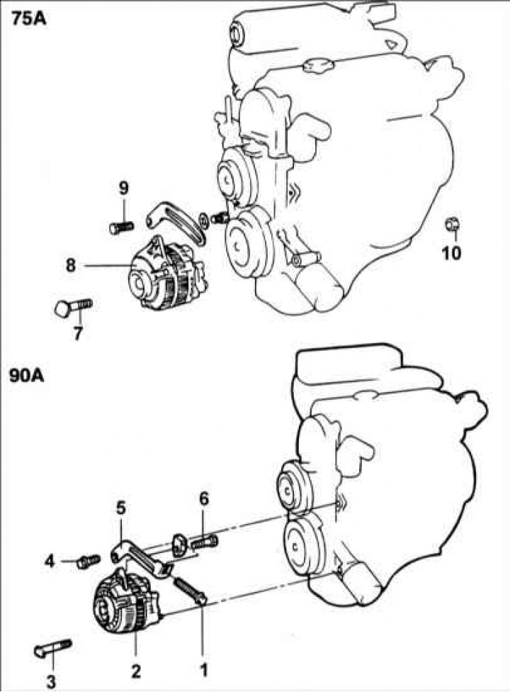
1 – adjusting bolt; 2 – generator 90 A; 3 – bolt, 20–25 Nm; 4 – bolt, 20–28 Nm; 5 – bracket; 6 – bolt, 12–15 Nm; 7 – bolt; 8 – generator 75 A; 9 – adjusting bolt; 10 – bolt, 20–25 Nm.
Removal
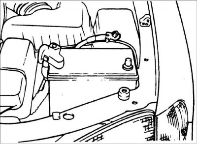
1. Disconnect the negative battery cable and the connectors from the radiator fan and condenser fan.
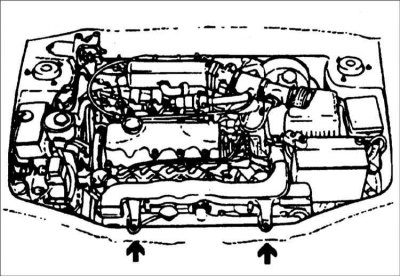
2. Remove the radiator mounting bolts.
3. Loosen the belt tension adjusting bolt and remove the alternator mounting bolt. Raise the vehicle.
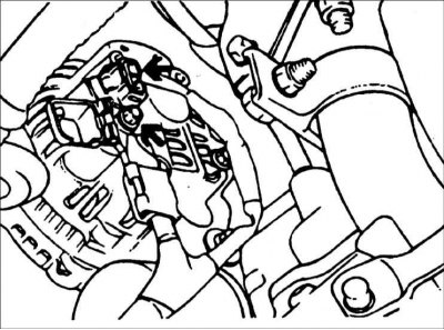
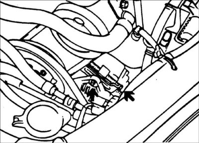
4. Disconnect the connector from the generator and the wire from the B+ terminal of the generator.
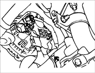
5. Remove the generator mounting bolt and nuts. Lift the radiator and remove the generator from the vehicle.
Disassembly (75 A)
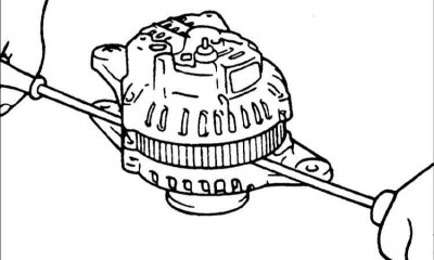
Warning! Place soft protective pads on the jaws of the vice to prevent damage to the generator parts.
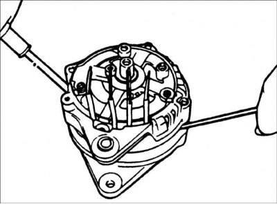
1. Secure the generator in a vice and remove the three tie bolts.
2. Insert the blade of two flat-head screwdrivers between the front cover and the stator magnetic core and remove the cover.
Warning: Do not insert screwdrivers too deeply, as this may damage the stator winding.
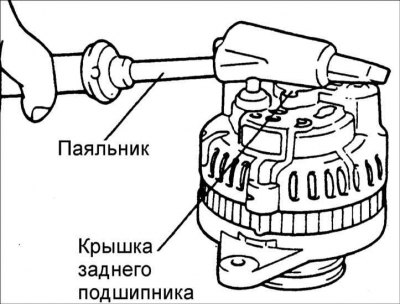
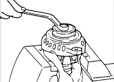
Warning! The back cover may be difficult to remove because of the ring that holds the outer ring of the rear bearing. To make it easier to remove the back cover, heat it with a 200W soldering iron. Do not use a hair dryer to heat it, as this may damage the diode unit.
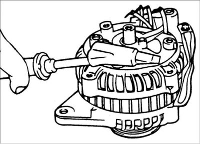
3. Clamp the rotor in a vice from the pulley side.
4. Remove the pulley mounting nut, then remove the spring washer, pulley and spacer sleeve.
5. Remove the front cover and two washers.
6. Remove the rotor from the vice.
7. Remove the screws securing the brush holder, rectifier and terminal B mounting nut.
8. Remove the stator from the rear cover.
9. Separate the oil deflector from the brush holder.
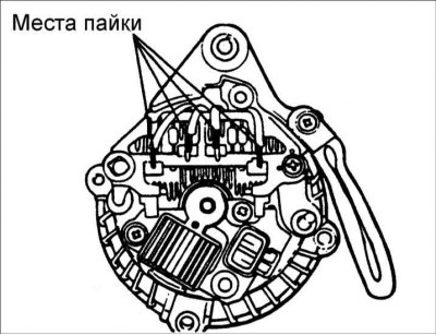
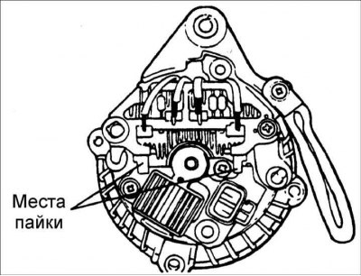
10. Unsolder the three wires from the diodes and remove the stator.
Warning! Perform desoldering for no more than 5 seconds, otherwise the rectifier diodes may be damaged.
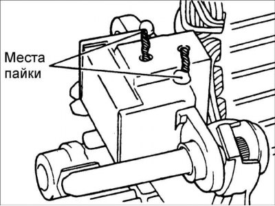
11. When separating the rectifier from the brush holder, unsolder the two plates soldered to the rectifier.
Check (75 A)
Rotor
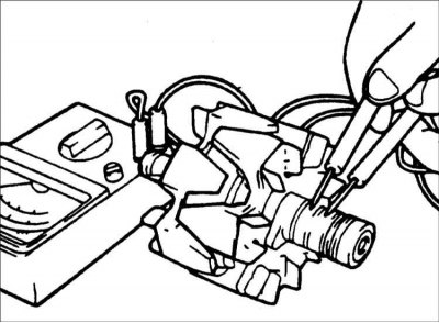
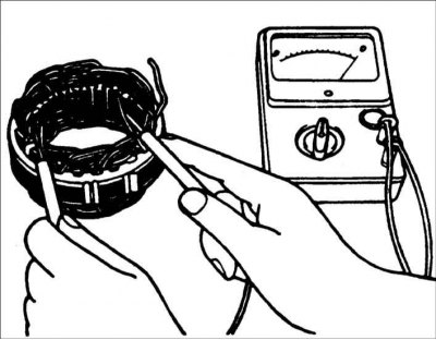
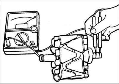
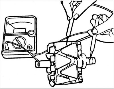
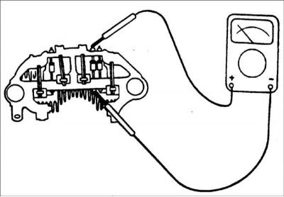
1. Use an ohmmeter to measure the resistance between the slip rings. If the resistance is extremely low, there is a short circuit in the rotor winding. If there is no conductivity, there is a break in the rotor winding, and the rotor must be replaced.
Resistance: 3.1 Ohm
2. Use an ohmmeter to check the continuity between the slip ring and the rotor anchor. If there is continuity, replace the rotor.
Stator
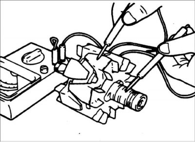
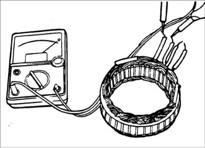
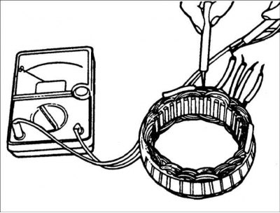
1. Use an ohmmeter to check the conductivity between the stator coil wires. If there is no conductivity, replace the stator.
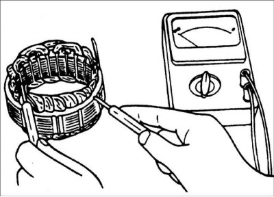
2. Use an ohmmeter to check the conductivity between the stator coils. If there is conductivity, replace the stator.
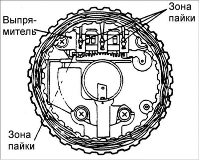
Checking the rectifier unit
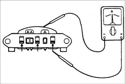
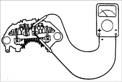
1. Check the continuity between the positive terminals of the rectifier and the stator coil terminal clamp. The ohmmeter should show continuity in one direction only. If there is continuity in both directions, the diode is broken and the rectifier must be replaced.
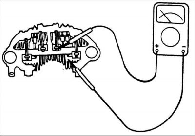
2. Check the continuity between the negative terminals of the rectifier and the stator coil terminal clamp. The ohmmeter should show continuity in one direction only. If there is continuity in both directions, the diode is broken and the rectifier must be replaced.
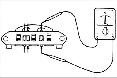
3. Use an ohmmeter to check the conductivity between the terminals of each of the three diodes. The ohmmeter should show conductivity in only one direction.
If there is conductivity in both directions, then the diode is broken and the rectifier needs to be replaced.
Replacing brushes
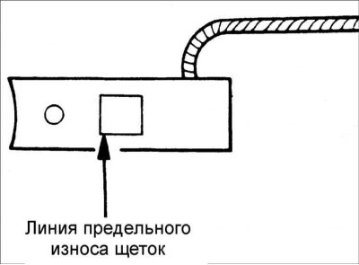
1. If the brushes are worn to the maximum permissible length, replace them.
2. Unsolder the braided wire and remove the spring and brush.
3. Install the brush spring and new brush into the brush holder.
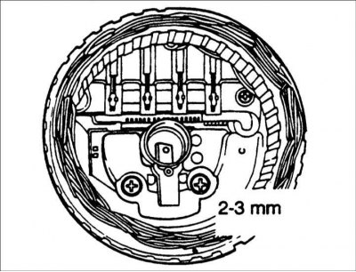
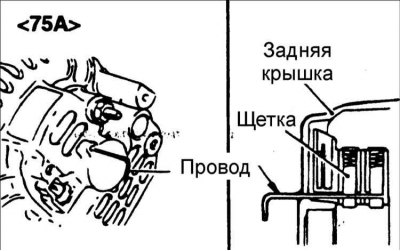
4. Insert the brush so that there is a distance of 2–3 mm between the wear limit line and the end of the brush holder.
5. Solder the braided wire to the brush holder.
Disassembly (90 A)
1. Unscrew the nuts securing terminal "B" to the rear cover.
2. If it is necessary to remove the stator, unsolder the four stator wires from the rectifier diodes.
Warning! Perform desoldering for no more than 5 seconds, otherwise the rectifier diodes may be damaged.
3. Remove the stator from the rear cover.
4. Remove the brush holder and rectifier.
5. Remove the four tie bolts.
6. Insert the blade of two flat-head screwdrivers between the front cover and the stator magnetic core and remove the cover.
Warning: Do not insert screwdrivers too deeply, as this may damage the stator winding.
Warning! The back cover may be difficult to remove because of the ring that holds the outer ring of the rear bearing. To make it easier to remove the back cover, heat it with a 200W soldering iron. Do not use a hair dryer to heat it, as this may damage the diode unit.
7. Clamp the rotor in a vice from the pulley side.
Warning! Place soft protective pads on the jaws of the vice to prevent damage to the generator parts.

8. Remove the pulley mounting nut, then remove the spring washer, pulley and spacer sleeve.
9. Remove the front cover and washers.
10. Remove the rotor from the vice.
11. When separating the rectifier from the brush holder, unsolder the two plates from the rectifier.
Check (90 A)
Rotor
1. Use an ohmmeter to measure the resistance between the slip rings. If the resistance is extremely low, there is a short circuit in the rotor winding. If there is no conductivity, there is a break in the rotor winding, and the rotor must be replaced.
Resistance: 3.1 Ohm
2.Use an ohmmeter to check the continuity between the slip ring and the rotor anchor. If there is continuity, replace the rotor.
Stator
1. Use an ohmmeter to check the conductivity between the stator coil wires. If there is no conductivity, replace the stator.
2. Use an ohmmeter to check the conductivity between the stator coils. If there is conductivity, replace the stator.
Checking the rectifier unit
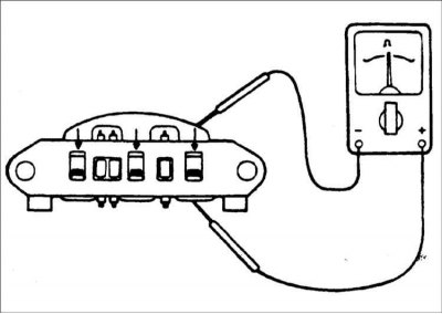
1. Check the continuity between the positive terminals of the rectifier and the stator coil terminal clamp. The ohmmeter should show continuity in one direction only. If there is continuity in both directions, the diode is broken and the rectifier must be replaced.
2. Check the continuity between the negative terminals of the rectifier and the stator coil terminal clamp. The ohmmeter should show continuity in one direction only. If there is continuity in both directions, the diode is broken and the rectifier must be replaced.
3. Use an ohmmeter to check the conductivity between the terminals of each of the three diodes. The ohmmeter should show conductivity in only one direction. If there is conductivity in both directions, the diode is broken and the rectifier must be replaced.
Assembly
1.Assembly is carried out in the reverse order of disassembly, taking into account the following.
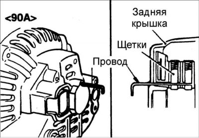
2.Before attaching the rotor to the back cover, insert the wire through the small hole in the back cover to fix the brushes in the retracted position. After installing the rotor, remove the wire.
Installation
1. Mount the alternator to the engine. Insert the central alternator mounting bolt, but do not screw the nut onto it.
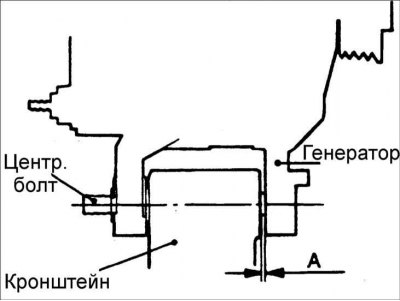
2. Move the generator to one side on the center generator mounting bolt and measure the distance between the generator support and the bracket.
3.Select a set of spacer washers that matches the measured distance.
4. Insert spacer washers and screw the nut onto the central generator mounting bolt. Further installation is carried out in the reverse order of removal.