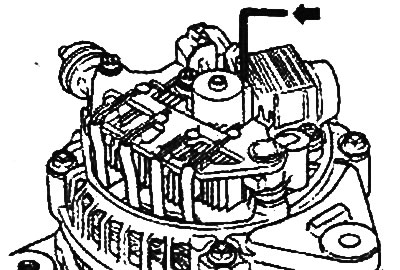
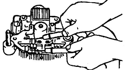
Removing the generator assembly.
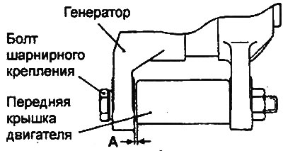
1 - adjusting bolt, 2 - generator, 3 - hinge bolt, 4 - generator adjusting bar.
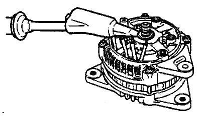
Generator.
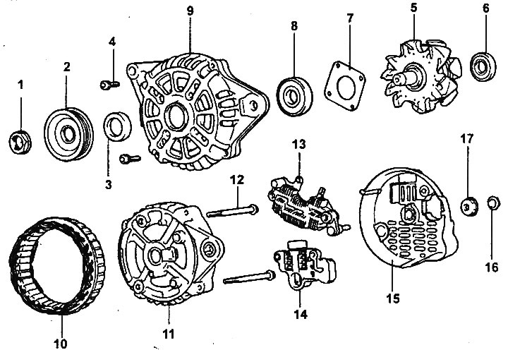
1 - hex nut, 2 - pulley, 3 - spacer sleeve, 4 - screw, 5 - rotor assembly, 6 - rear generator bearing, 7-bearing holder, 8 - front generator bearing, 9 - front generator bracket, 10-stator assembly, 11 - rear generator bracket, 12 - bolt, 13-rectifier unit, 14-regulator assembly, 15-generator cover, 16-nut, 17-isolation cover of the output "B"
Removal
1. Disconnect the cable from the negative terminal of the battery.
2. Disconnect the radiator fan connector and the air conditioner condenser fan connector.
3. Unscrew the radiator support mounting bolts.
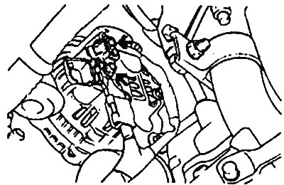
4. Loosen the adjusting bolt on the alternator adjusting bar and remove the lock bolt. Then lift the vehicle.
5. Disconnect the generator connector and disconnect the wire from the "B" terminal of the generator.
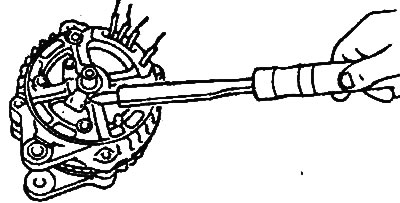
6. Remove the generator drive belt. Unscrew the nut and bolt of the generator hinge mount.
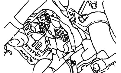
7. Lift the radiator and remove the generator assembly.
Installation
1. Install the generator in place and insert the pivot bolt. (Do not tighten the pivot bolt nut.)
2. Push the alternator forward and determine how many spacers (each 0.198 mm thick) need to be inserted between the front alternator stand and the front engine cover (gap "A" in the figure).
Note: Choose enough spacers so that they do not fall out when you try to insert them into the gap.
3. Insert spacers (gap "A" in the figure), connect and tighten the nut of the pivot bolt.
4. After installation is complete, adjust the tension of the generator drive belt.
Disassembly
1. Loosen the four tie bolts.
2. Insert a flat-blade screwdriver between the front generator bracket and the stator and, using the screwdriver as a lever, pry (down) the front generator bracket.
Note:
- Do not insert the screwdriver too deeply to avoid damaging the stator winding.
- It may be difficult to remove the rear alternator bracket because of the retaining ring used to secure the rear bearing. To make removing the rear bracket easier, heat the bearing assembly with a 200 watt soldering iron. Do not use a heat gun as this may damage the rectifier diodes.
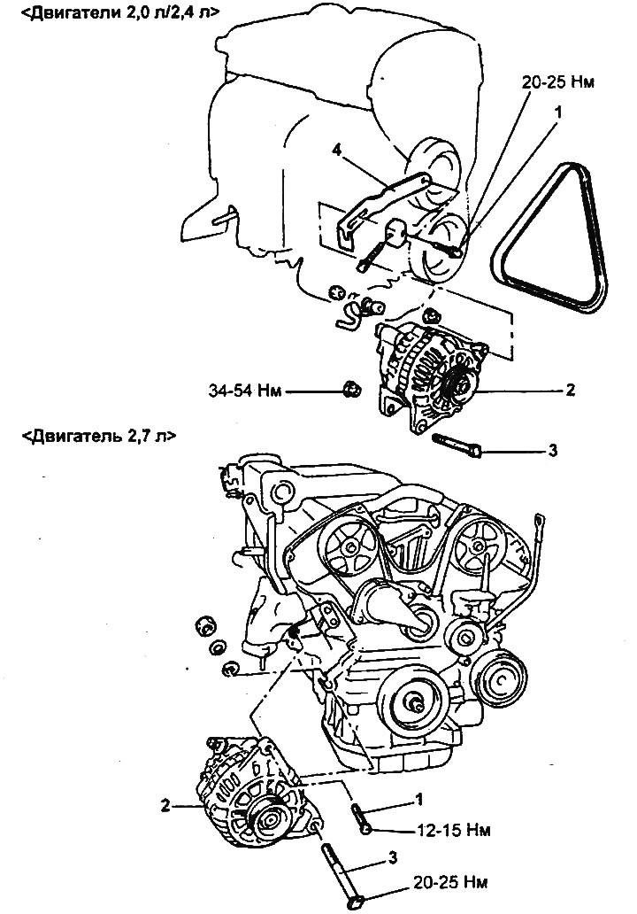
Engines 2.0 l / 2.4 l. |
Engine 2.7 l. |
Engines 2.0 l / 2.4 l. |
Engine 2.7 l. |
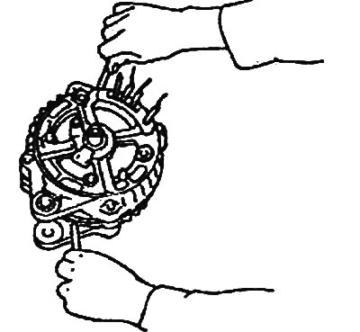
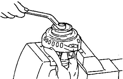
3. Clamp the rotor in a soft jaw vice with the pulley side facing up.
Caution: Be careful not to damage the rotor with the vice jaws.
Engines 2.0 l / 2.4 l. |
Engine 2.7 l. |
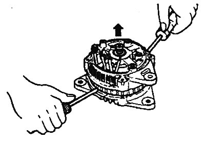
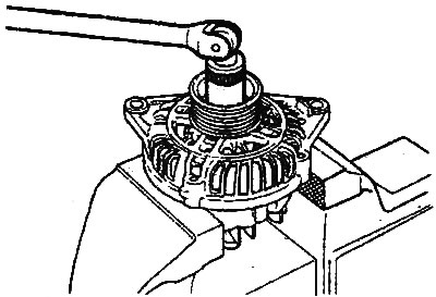
4. Loosen the pulley mounting nut, remove the spring washer, then remove the pulley and spacer sleeve.
5. Remove the front generator bracket and two O-rings.
6. Remove the rotor from the vice.
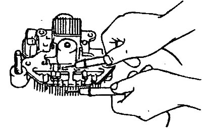
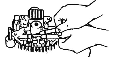
7. Unscrew the screws securing the brush holder and rectifier unit. Then unscrew the nut of the generator terminal "B".
8. Remove the stator assembly from the rear generator bracket.
9. Remove the dust ring from the brush holder.
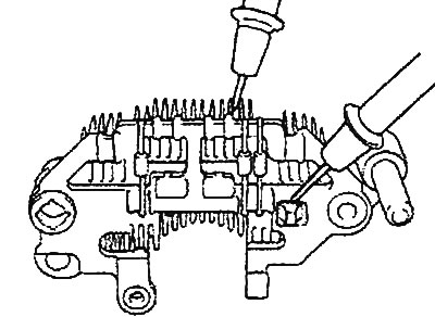
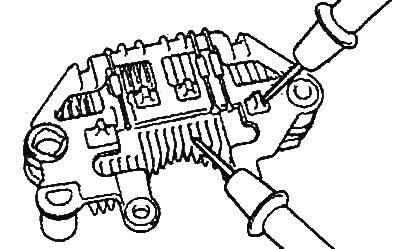
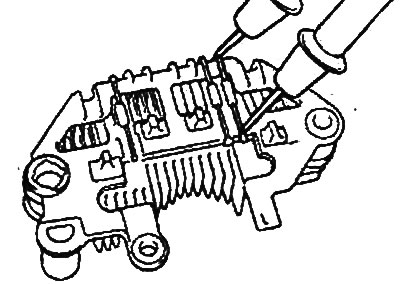
10. Before removing the stator, unsolder the three stator winding wires from the main diodes of the rectifier unit.
Note:
- When soldering/unsoldering contacts, be careful that the heat from the soldering iron has as little effect on the diodes as possible. Perform these operations as quickly as possible.
- Be careful not to apply excessive force to the diode contacts.
11. Before disconnecting the rectifier block from the brush holder, unsolder the two contacts soldered to the rectifier block.

Examination
Rotor
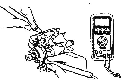
1. Check for breaks in the rotor winding.
Check for a closed circuit between the contact rings. If the resistance is too low (approaching 0), this means there is a short circuit. In the event of a break in the rotor winding circuit or a short circuit, replace the rotor assembly.
- Resistance approx: 3.1 Ohm
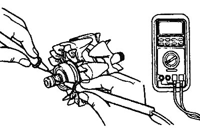
2. Check for short circuit of rotor winding to ground. Check for closed circuit between slip ring and core. If there is a short circuit (short circuit to ground), replace rotor assembly.
Stator
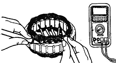
1. Check for a break in the stator winding. Check for a closed circuit between the stator winding terminals. If the winding circuit is open (resistance tends to infinity), replace the stator assembly.
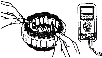
2. Check for short circuit of the stator winding to ground (i.e. absence of closed circuit between the stator winding and the core). If the circuit is closed (resistance tends to zero), replace the stator assembly.
Checking the positive terminal of the rectifier block
1. Using an ohmmeter, check that the circuit between the terminal of the positive diodes of the rectifier unit and the terminal of the stator winding is closed (low resistance).
2. Change the polarity of the ohmmeter probes and measure the resistance (if the resistance is low, i.e. the circuit is closed in both directions, then the diode is "broken"). Replace the rectifier unit as a whole.
Engines 2.0 l / 2.4 l. |
Engine 2.7 l. |
Checking the negative terminal of the rectifier unit
1. Using an ohmmeter, check that the circuit between the terminal of the "negative" diodes of the rectifier unit and the terminal of the stator winding is closed (low resistance).
2. Change the polarity of the ohmmeter probes and measure the resistance (if the resistance is low, i.e. the circuit is closed in both directions, then the diode is "broken"). Replace the rectifier unit as a whole.
Engines 2.0 l / 2.4 l. |
Engine 2.7 l. |
Checking three diodes of the rectifier block
1. Test the three diodes by connecting an ohmmeter to both terminals of each diode. For each diode, the circuit should be complete in only one direction.
2. If there is no closed circuit in both directions (or if there is a closed circuit in both directions), the diode is faulty and the rectifier unit (together with the cooling radiator) must be replaced.
Engines 2.0 l / 2.4 l. |
Engine 2.7 l. |
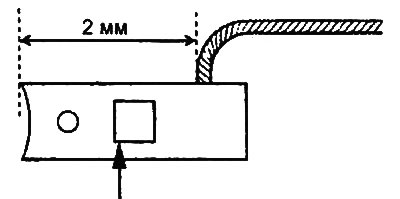
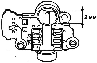
Replacing brushes
1. Measure the brush protruding length shown in the figure and replace the brushes if the measured value is less than the maximum permissible value.
- Limit value: 2mm or less
Engines 2.0 l / 2.4 l. |
Engine 2.7 l. |
2. If it is necessary to remove the brush, unsolder the brush wire from the brush holder.
3. When installing a new brush, insert it into the brush holder and solder the brush wire.
Assembly
Assembly is carried out in the reverse order of disassembly.
When performing assembly operations, please note the following:
Before installing the rotor into the rear bracket, insert a thin wire into the small hole in the rear bracket to secure the raised brushes. The wire should be removed after installing the rotor.