
Contents: Checking the generator output…⇓ Checking the generator output current ⇓ Checking the regulated voltage…⇓
Checking the generator output voltage drop
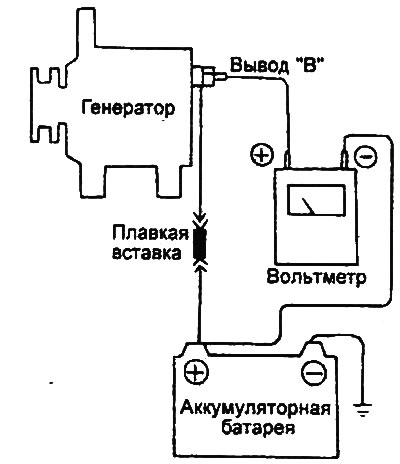
This test is necessary to assess the condition of the wiring from the "B" terminal of the generator to the positive terminal of the battery (including the fuse link).
Preparing for the test
1. Turn the ignition switch key 8 to the "OFF" position.
Note: To accurately determine the fault at the connection points, make sure that both terminals or their connections are not disturbed when performing the test.
2. Connect a digital voltmeter to the "B" terminal of the generator and the positive terminal of the battery. Connect the "plus" wire of the voltmeter to the "B" terminal of the generator, and the "minus" wire of the voltmeter to the positive terminal of the battery.
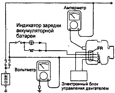
Engines 2.0 l / 2.4 l. |
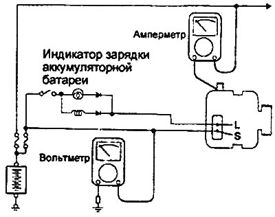
Engines 2.7 l. |
Conditions for conducting the inspection
1. Start the engine.
2. Read the voltmeter readings with the engine idling and the generator load on (headlights, heater fan, etc.).
Analysis of results
1. The voltmeter should show a voltage drop corresponding to the nominal value.
- Nominal value: maximum 0.2V
2. If the voltage drop is greater than the nominal value (greater than 0.2 V), the cause is most likely a fault in the wiring. In this case, check the wiring between the generator terminal "B" and the positive terminal of the battery (including the fuse link). Check for faults (poor contact) in the connectors and connections, discoloration of the wire insulation (due to overheating), etc. Fix the fault and recheck.
3. After completing the check, let the engine idle. Turn off the headlights, heater fan and other loads, then turn the ignition switch to the "OFF" position.
Checking the generator output current
Engines 2.0 l / 2.4 l. |
Engines 2.7 l. |
This test determines whether the generator output current matches the rated value.
Preparing for the test
1. Before starting the test, perform the following checks and repair if necessary:
- a) Check the condition of the battery installed in the vehicle.
Note: The battery used for this test must be slightly discharged. A fully charged battery is not suitable for accurately performing this test as the load created will not be sufficient.
- b) Check the tension of the generator drive belt.
2. Turn the ignition key to the "OFF" position.
3. Disconnect the cable from the negative terminal of the battery.
4. Disconnect the standard wire from the generator terminal "B".
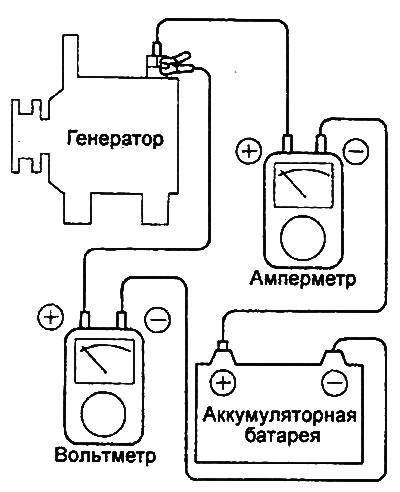
5. Connect an ammeter (DC, 0-100 A range) in series between the generator terminal "B" and its standard wire. Make sure that the ammeter's "minus" wire is connected to the standard wire disconnected from the generator.
Note: Make sure each connection is secure and tight, as the terminals will carry a large amount of current. Do not use clips (alligator clips) when connecting to an electrical circuit.
6. Connect a voltmeter (0-20 V scale) between the "B" terminal of the generator and the "ground". Connect the "positive" wire of the voltmeter to the "B" terminal of the generator, and then the "minus" wire of the voltmeter to a suitable "ground" (to the body).
7. Connect the test tachometer according to the manufacturer's instructions. Connect the wire to the negative terminal of the battery.
Verification procedure
1. Make sure the voltmeter shows battery voltage. If the voltmeter shows 0 V, there is an open circuit between the generator terminal "B" and the negative terminal of the battery. Check for a blown fuse or a poor ground connection.
2. Start the engine and turn on the headlights.
3. Turn on the high beam headlights and set the heater electric fan switch to the "HIGH" position, then sharply increase the engine crankshaft speed to 2500 rpm and read the maximum value of the generator output current (shown by the ammeter).
Note: After the engine starts, the charging current drops quickly. Perform the test as quickly as possible to measure the maximum value of the generator output current.
Analysis of results
1. The ammeter readings should be above the maximum permissible value. If the ammeter readings are below the maximum permissible value, and the generator output circuit "B" is in good condition, remove the generator from the car and test it on a bench.
- Maximum permissible value: minimum 63.0 A
Note:
- The generator's nominal output power is stamped on a plate attached to the generator body.
- The value of the output current varies depending on the generator load and the generator housing temperature. Therefore, the nominal output power may not be achieved. In such cases, to increase the electrical load (in order to discharge the battery), turn on the high beam headlights for a while or connect the external lighting system of another car.
- The nominal value of the generator output current may also not be obtained due to overheating of the generator housing or too high ambient air temperature. In such cases, allow the generator to cool down and recheck.
2. After completing the generator output current test, gradually reduce the engine crankshaft speed to idle speed, then turn off the ignition.
3. Disconnect the cable from the negative terminal of the battery.
4. Remove the ammeter, voltmeter and control tachometer.
5. Connect the standard wire to the "B" terminal of the generator.
6. Connect the cable to the negative terminal of the battery.
Checking the regulated voltage (checking the voltage regulator)
This test determines if the generator voltage regulator is properly controlling the generator output voltage.
Preparing for the test
1. Before starting the test, perform the following checks and repair if necessary:
- a) Check that the battery installed in the vehicle is fully charged.
Note: For the procedure to check the battery, see the Battery section.
- b) Check the tension of the generator drive belt.
2. Turn the ignition key to the "OFF" position.
3. Disconnect the cable from the negative terminal of the battery.
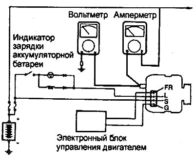
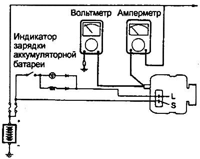
4. Connect a digital voltmeter between the alternator "S (L)" terminal and ground. First connect the voltmeter's "plus" wire to the alternator "S (L)" terminal, then the "minus" wire to a suitable ground (the body or the negative terminal of the battery).
5. Disconnect the standard wire from the generator terminal "B".
6. Connect an ammeter (DC, 0-100 A range) in series between the generator terminal "B" and the disconnected standard wire. Connect the ammeter's "minus" wire to the disconnected standard wire.
7. Connect the test tachometer according to the manufacturer's instructions. Connect the wire to the negative terminal of the battery.
Engines 2.0 l / 2.4 l. |
Engines 2.7 l. |
Verification procedure
1. Turn on the ignition and make sure that the voltmeter shows the specified voltage value. If the voltmeter shows 0 V, then either there is an open circuit between the "S (L)" terminal of the generator and the positive terminal of the storage battery, or the fuse has burned out.
- Nominal value: battery voltage
2. Turn off all lights and additional electrical equipment. Start the engine.
3. Set the engine crankshaft speed to 2500 rpm. Read the voltmeter readings when the generator output current is 10A or less.
Analysis of results
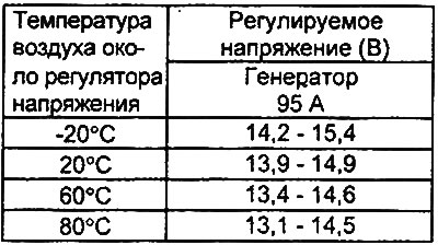
1. If the voltmeter readings correspond to the nominal values of the regulated voltage given in the table, then the voltage regulator is in good working order. If the voltmeter readings do not correspond to the range of nominal values, then either the voltage regulator or the generator is faulty.
Table. Nominal values of regulated voltage.
2. After completing the check, gradually reduce the engine speed to idle speed, then turn off the ignition.
3. Disconnect the cable from the negative terminal of the battery.
4. Disconnect the ammeter, voltmeter and reference tachometer.
5. Connect the standard wire to the "B" terminal of the generator.
6. Connect the cable to the negative terminal of the battery.