Contents: Removal and installation ⇓ Examination ⇓
Removal and installation
1. Remove the ignition system fuse.
2. Remove the center cover.
3. Disconnect the ignition wires from the ignition coils and disconnect the high-tension spark plug wires.
Note: When disconnecting the spark plug wire, be sure to hold only the rubber cap of the wire. If the spark plug wire is disconnected by pulling on the wire itself, internal breaks in the wire circuit may result.
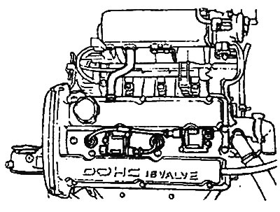
4. Remove the coils.
5. Installation is carried out in the reverse order of removal.
Examination
1. Measuring the resistance of the primary winding of the ignition coil.
- a) Connect the wire from the negative terminal of the 3 V power source to terminal "2" of the ignition coil. Then check the condition of the circuit between terminals "3" and "2" of the ignition coil with the positive terminal wire of the power source disconnected and connected from terminal "1" of the ignition coil.
Table. Checking the primary winding of the ignition coil.
| Pin "1" and positive terminal of power supply | The circuit between terminals "3" and "2" |
| United | The circuit is closed (resistance is approximately 0.86 Ohm) |
| Not connected | The circuit is open |
[The publication is borrowed from the website: HYUNDAIBOOK.ru]
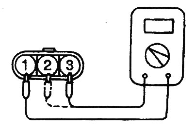
- b) Replace the power transistor if it is faulty.
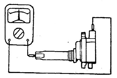
2. Measuring the resistance of the secondary winding of the ignition coil.
Measure the resistance between the high voltage terminal and the spark plug wire terminal of the ignition coil.
- Nominal value: about 12.1 kOhm
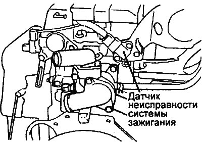
3. Checking the ignition system malfunction sensor.
Note: An analog multimeter should be used when checking.
- a) Check the resistance between terminals "1" and "2" of the sensor connector.
- Nominal value: 0.1 ohm or less
- b) If the measured value is greater than the permissible value, replace the sensor assembly.