
Preparing for the test
Turn the ignition key to the "OFF" position.
Note: To accurately determine the fault at the connections, make sure that both terminals or their connections are not disturbed when performing the test.
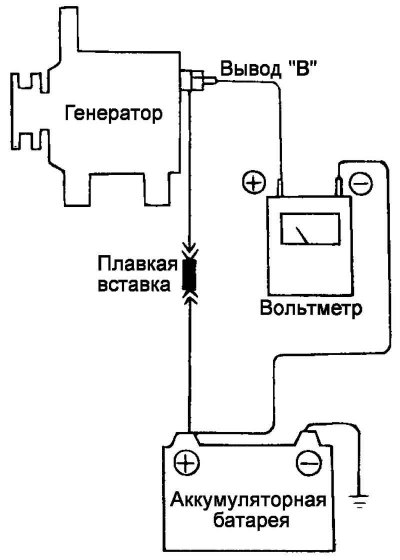
Fig. 7.19. Generator output voltage test circuit
(The full version is located on the website: «HyundaiBook.ru»)
Connect a digital voltmeter to the "B" terminal of the generator and the (+) terminal of the battery. Connect the (+) lead of the voltmeter to the "B" terminal of the generator and the (–) lead of the voltmeter to the (+) terminal of the battery (Fig. 7.19).
Conditions for conducting the inspection
Start the engine.
Read the voltmeter readings with the engine idling and the generator load on (headlights, heater fan, etc.).
Analysis of results
The voltmeter should show a voltage drop corresponding to the nominal value.
Nominal value: maximum 0.2V.
If the voltage drop is greater than the nominal value (more than 0.2 V), then the cause is most likely a fault in the wiring.
In this case, check the wiring between the generator terminal "B" and the (+) terminal of the battery (including the fuse). Check for faults (poor contact) in the connectors and connections, discoloration of the wire insulation (due to overheating), etc. Fix the fault and recheck.
After completing the check, let the engine idle. Turn off the headlights, heater fan and other loads, then turn the ignition switch to the "OFF" position.