
Removal
1. Remove the timing belt, front cover, flywheel, cylinder head and oil pan.
2. Remove the rear cover from the cylinder block and the rear crankshaft seal ring.
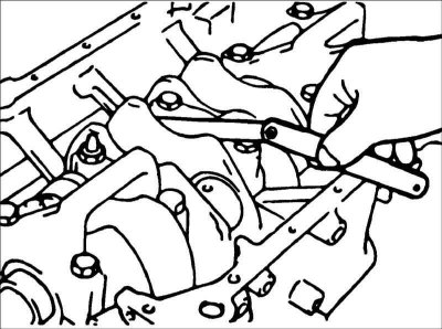
3. Loosen the nuts and remove the connecting rod caps.
Caution: Mark the crankshaft main bearing caps to ensure that they are installed in their proper locations and in the same position.
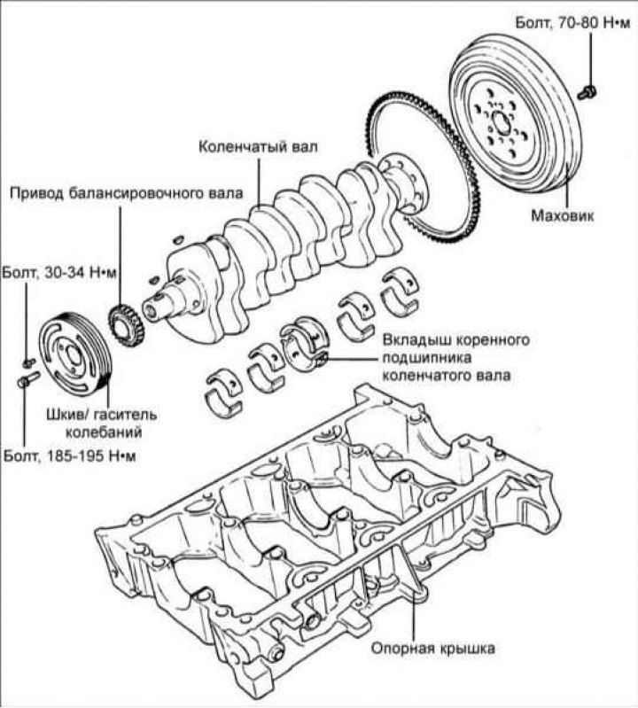
4. Unscrew the bolts and remove the crankshaft main bearing cap and the crankshaft.
Examination
1. Check the journals of the main and connecting rod bearings of the crankshaft for wear and tear. Check the crankshaft oil holes for clogging.
2. Using a micrometer, measure the diameters of the crankshaft journals in two diametrically opposite directions. If there is taper or ovality, regrind the crankshaft.
- Main journal diameter: 60.002-60.020 mm
- Connecting rod diameter: 50.008-50.026 mm
Connecting rod and main bearing shells
Check the connecting rod and main bearings for local corrosion, wear and other damage. Replace the liners if necessary.
Measuring the clearance of main and connecting rod bearings
To measure the main and connecting rod bearing clearance, measure the crankshaft journal diameters and the corresponding bearing inside diameters. The clearance value is the difference between the inner diameter of the bearing and the corresponding diameter of the crankshaft journal.
- Crankshaft main bearing clearance: 0.024–0.042 mm
- Crankshaft connecting rod bearing clearance: 0.024–0.042 mm
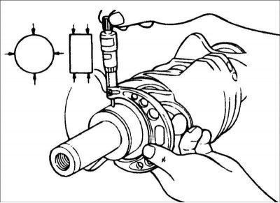
Plastigauge method
The most accurate and convenient way to measure the clearance of main and connecting rod bearings is to use the Plastigauge plastic calibrated rod
1. Clean the main and connecting rod journals of the crankshaft from grease, and blow out the lubrication holes with compressed air.
2. Install the main bearing shells onto the engine cylinder block. Cut pieces of Plastigauge plastic rod equal to the width of the bearings and place them axially on the crankshaft main bearing shells.
3. Install the crankshaft onto the main bearing shells in the cylinder block. Install the main bearing shells and support cover in accordance with the markings. Tighten the crankshaft main bearing cap mounting bolts in a specific sequence. Do not rotate the engine crankshaft when measuring the crankshaft main bearing clearance. Remove the bolts and the crankshaft main bearing cap. Using a measuring template, measure the width of the deformed Plastigauge plastic rod and determine the gap size.
Oil sealing rings
Check the front and rear oil seal rings for damage or wear on the sealing lips. If any defects are present, replace the sealing ring.
Bearing support cap
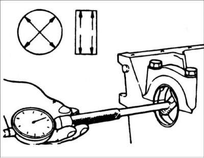
After installing the bearing cap, rotate the crankshaft and ensure that it rotates freely and smoothly and that its axial clearance is within specification. Crankshaft axial clearance: 0.09 – 0.32 mm.
[The original can be found on the resource www.hyundaibook.ru]
Drive plate
Replace a warped, damaged or cracked drive plate.
Flywheel
1. Check the condition of the flywheel surface in contact with the clutch disc. If significant wear is present, replace the flywheel.
2. Check the runout of the flywheel surface in contact with the clutch disc. Runout: 0.13 mm³.
3. Check the flywheel ring gear for damage and wear and replace it if necessary.
Installation
1. Install the upper main bearing shells with oil supply grooves to the engine block. When reinstalling the liners, place them in the same locations they were in before removal.
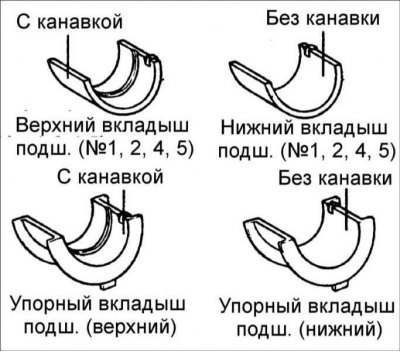
2. Install the non-grooved main bearing shells into the crankshaft main bearing cap.
3. Install the lower center main bearing shell without the groove. Install the upper center main bearing shell with groove.
4. Before installing the crankshaft, apply a thin layer of clean engine oil to all sliding surfaces. Install the crankshaft onto the main bearing shells in the cylinder block.
5. Install the support cover using Loctite 5205 sealant.
6. Tighten the support plate mounting bolts to the required torque. Tightening torque: – 15 mm: 28–32, tighten further by 120° – 12 mm: 33.7–37.7.
7. Tighten the bolts in 4 or 5 passes.
8. Turn the crankshaft and check that it rotates easily and smoothly. Place the dial indicator tip on the front end of the crankshaft. Move the crankshaft along the axis until it stops and set the dial indicator scale to zero. Move the crankshaft along the axis in the other direction until it stops and read the axial play values on the indicator scale.
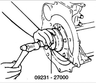
9. Lubricate the outer surface of the new O-ring with engine oil. Using special tool 09231–21000, install the sealing ring into the cover seat until it stops.
Cars with manual transmission
10. Install the flywheel and tighten the bolts to specification. Tightening torque: 70–80 Nm.
Cars with automatic transmission
11. Install the drive plate and secure with bolts, tightening them to specification. Tightening torque: 70–80 Nm.