
Contents: Examination ⇓ Installation ⇓
Examination
Piston
1. Inspect the outer surface of the piston for damage, wear or uneven wear. Replace the piston if necessary.
2. Check the piston pin by inserting it into the piston hole. The piston pin should enter the piston smoothly when pressed by hand (at room temperature).
Piston rings
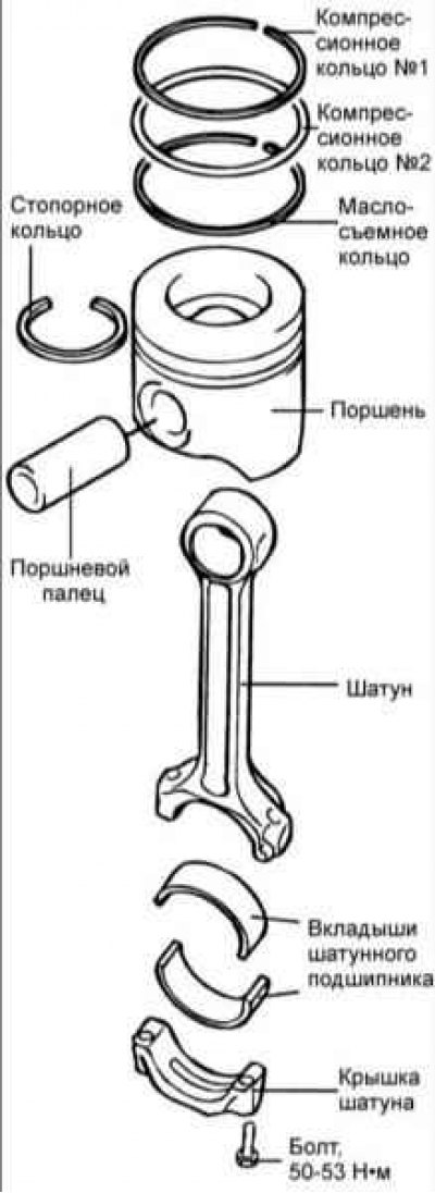
1. Inspect each piston ring for damage or uneven wear. Replace piston rings if necessary.
2. When replacing the piston, it is also necessary to replace the piston rings.
3. Insert a new piston ring into the piston groove and use a feeler gauge to measure the gap between the piston ring and the groove wall. If the clearance exceeds the maximum permissible value, replace the piston.
Clearance between piston ring and piston groove:
- Second compression ring: 0.065–0.11 mm
- Oil scraper ring: 0.03–0.07
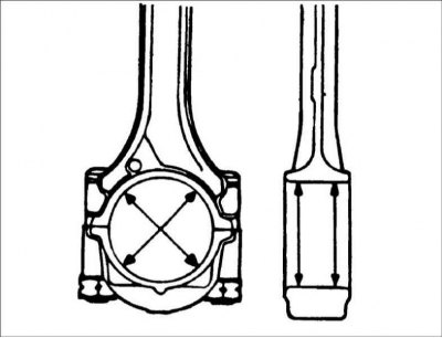
4. Measure the piston ring gap by manually inserting the piston ring into the engine cylinder. Use the bottom of the piston to push the piston ring into the bottom of the cylinder.
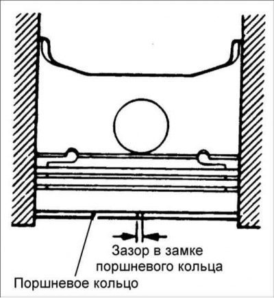
5. Use a feeler gauge to measure the gap in the piston ring joint.
Piston ring gap:
- First compression ring: 0.2–0.3 mm
- Second compression ring: 0.30–0.45 mm
- Oil scraper ring: 0.20-0.45 mm
- Maximum clearance: 0.8 mm
Connecting rod bearing shells
1. Check the working surfaces of the connecting rod bearing shells for stripes, scratches, local corrosion, wear and other damage. Replace the liners if necessary. If the working surfaces of the connecting rod bearing shells are badly damaged, check the condition of the crankshaft connecting rod journals. If the crankshaft is also damaged, replace it or regrind the journals to the next smaller size for reuse.
2. Measure the inner diameter of the connecting rod bearing shells and the diameter of the crankshaft journals. If the oil clearance exceeds the permissible limits, replace the bearings and, if necessary, the crankshaft.
- Oil clearance in connecting rod bearings: 0.024–0.042 mm
- Maximum permissible gap: 0.10 mm
Installation
Connecting rod, piston pin and piston
1. Connect the piston to the connecting rod.
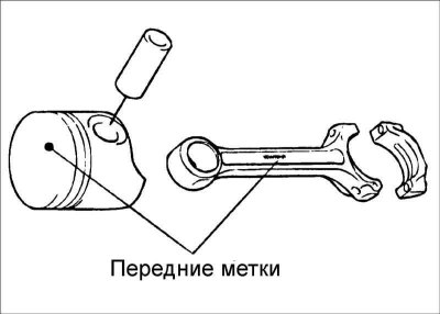
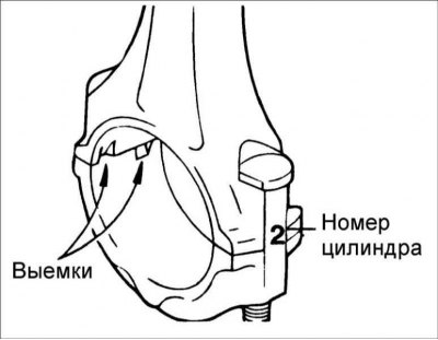
2. Align the front marks and insert the piston pin. The piston pin should enter the piston smoothly when pressed by hand (at room temperature). If there is a large gap, replace the piston pin.
Piston rings
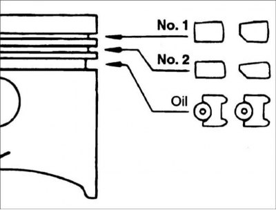
1. Install the oil scraper ring expander and oil scraper ring onto the piston. Using piston ring spreader pliers, install compression ring #2, then install compression ring #1. Make sure the marks on the piston rings are facing the piston bottom.
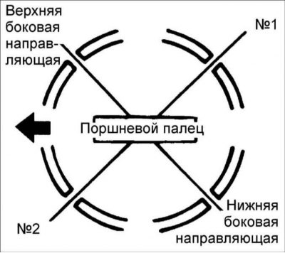
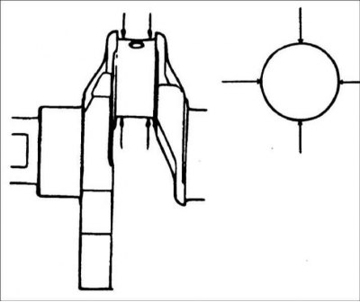
2. Position the piston ring locks as shown in the figure.
3. Install the piston with piston rings over the first cylinder, with the mark on the piston facing the front of the cylinder block.
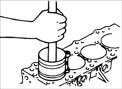
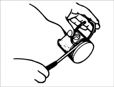
4. Using a special tool, compress the piston rings onto the piston. Using a hammer handle, press the piston into the cylinder until the lower head of the connecting rod is seated on the crankshaft journal.
5. Install the connecting rod bearing into the connecting rod cap. Install the connecting rod cover and secure with nuts. Tightening torque: 25 Nm, tighten further by 90°.
Warning: Do not reuse connecting rod cap bolts more than three times.
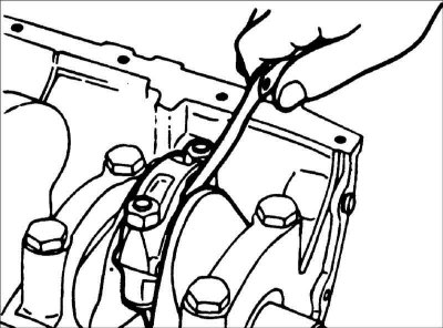
6. Using a feeler gauge inserted between the connecting rod and the crankshaft, measure the connecting rod side clearance.
- Nominal side clearance of connecting rod: 0.10–0.35 mm
- Maximum allowable gap: 0.40 mm