
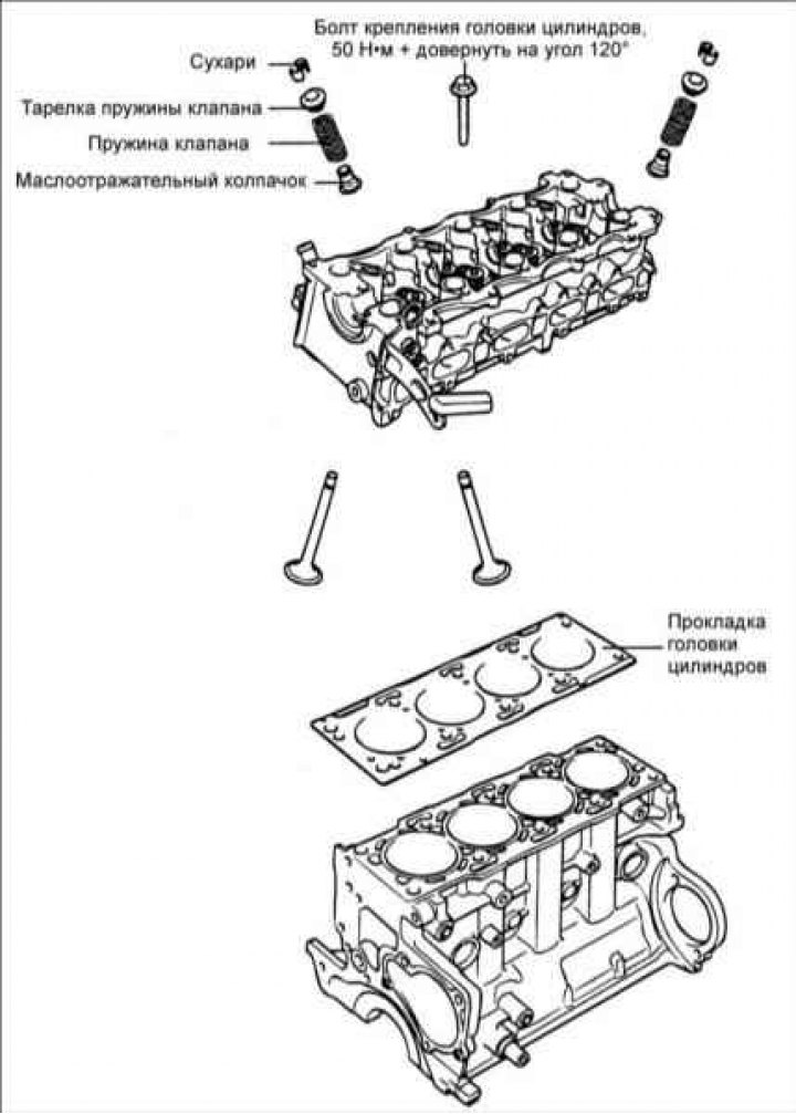
Disassembly
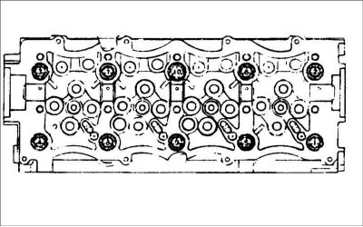
1. In the sequence shown in the figure, in 2–3 passes, unscrew the cylinder head mounting bolts.
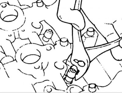
2. Using special tool 09222 – 27300, compress the valve spring and remove the crackers from the valve stem. Slowly release the spring compressor and remove the valve spring, spring retainer and valve from the cylinder head.
Note: Prepare numbered plastic bags or containers for storing valves.
3. Use pliers to remove the oil deflector cap.
Caution: Do not reuse the valve stem seal.
Examination
Cylinder head
1. Inspect the cylinder head for damage, cracks, oil and coolant leaks. Replace the cylinder head if necessary.
2. Remove scale, sealant and carbon deposits. Blow out the lubrication channels with compressed air.
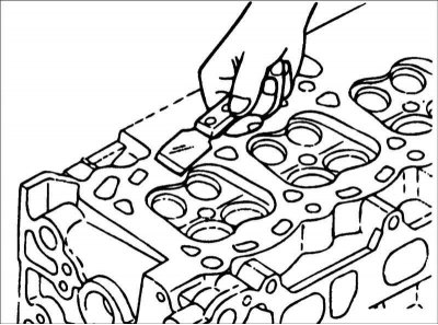
3. Using a metal ruler and feeler gauge in six directions, check the flatness of the cylinder head. If necessary, regrind the cylinder head.
Standard deviation from flatness:
- by width 0.03 mm;
- by length 0.09 mm;
- diagonally 0.012 mm.
Valves
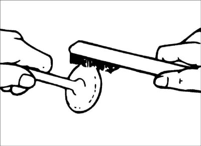
1. Clean the valve with a wire brush.
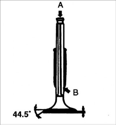
2. Inspect each valve for wear, damage and deformation in areas A and B and repair or replace if necessary. If the end of the rod is pitted or worn, re-chamfer as necessary. This restoration should be limited to minimal metal removal.
Also check the thickness of the working edges.
Valve working edge thickness:
- Intake valves: 1.16 mm
- Exhaust valves: 1.30 mm
Valve spring
1. Inspect each valve spring for cracks or damage. Measure the length of the spring in its free state.
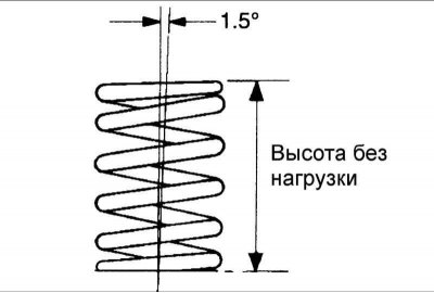
2. Place the spring on a flat horizontal surface and measure the deviation of the top of the spring from the vertical plane.
- Spring length without load: 39.14 mm
- Spring length under 21.4 kg load: 32 mm
- Permissible deviation of the spring from the vertical plane: no more than 1.5°
- Maximum permissible reduction in length: -1 mm
- Maximum permissible deviation of the spring from the vertical plane: no more than 4°
Valve guide bushings
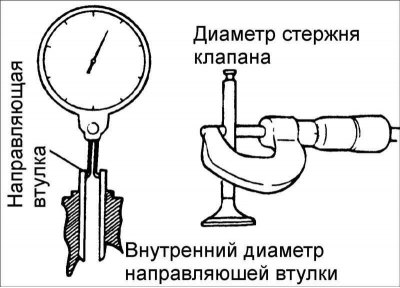
Check the clearance between the valve stem and the valve guide. If the clearance exceeds the maximum permissible value, replace the valve guide bushing with a bushing of an increased repair size.
Clearance between valve stem and valve guide:
- Intake valves: 0.022–0.067 mm
- Exhaust valves: 0.005–0.095 mm
Maximum permissible clearance between the valve stem and the valve guide bushing:
- Inlet valves: 0.1 mm
- Exhaust valves: 0.15 mm
Valve seat insert
Check the valve seat for overheating and damage to the working surface in contact with the valve disc. Repair or replace the valve seat if necessary.
Before replacing or repairing the valve seat, check the valve guide for wear. If the valve guide is worn, replace it.
Assembly
1. Clean the parts before installation.
2. Apply a thin layer of motor oil to all sliding surfaces.
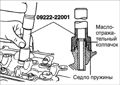
1. Install the spring seat.
2. Using special tool 09222–27200, install the oil seal.
1. Do not reuse old valve stem seals.
2. Incorrect installation of the oil deflector cap adversely affects its working edge due to eccentricity and leads to leakage of engine oil through the valve guide bushings. When installing, be careful not to twist the oil seal.
3. Lubricate the valve stem with engine oil and install the valve. When installing the valve, do not apply too much force to avoid damaging the oil seal. Check the smooth movement of the valve.
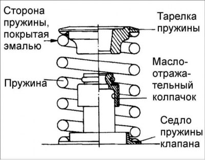
4. Install the springs and spring retainers. The springs must be installed with the enamel side facing the spring holders.
5. Using special tool 09222–27300, compress the spring. Install the crackers and remove the special spring compressor.
Caution: When compressing the spring, make sure that the oil seal is not pinched by the spring compressor.
6. Clean all mating surfaces of the cylinder block and cylinder head.
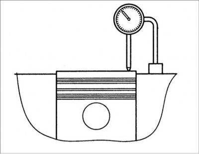
7. Determine the thickness of the cylinder head gasket:
- measure the piston protrusion set at TDC in relation to the mating surface of the cylinder block;
- depending on the piston protrusion value, select the gasket thickness according to the table. The piston protrusion value required is the average value of eight measurements. Even if one dimension exceeds the permissible limits, the gasket thickness must be selected based on the measurement of the protrusion of that point.
The text is taken from an online source (HyundaiBook.ru)
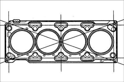
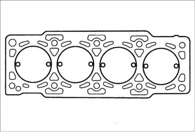
8. Install the new cylinder head gasket with the marked surface facing the cylinder head.
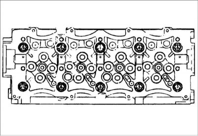
9. Tighten the cylinder head bolts in the sequence shown in the figure. Tightening torque: 50 Nm, further tightened by 120°.
Performance | 2.0 l | ||
| Mean piston protrusion value | 0.194–0.337 mm | 0.337–0.440 mm | 0.440–0.542 mm |
| Gasket thickness | 1.13±0.05 mm | 1.23±0.05 mm | 1.33±0.05 mm |
| Limit of each rank | 0.43 mm | 0.53 mm | – |
| Identification marks | 001 | 002 | 003 |