
1. Install the drive shaft oil seal using the special tool (09431-21000).
2. Install the front oil seal using the special tool (09431-21000).
3. Install the secondary shaft oil guide.
4. Using a special tool (09532-11500) install the outer ring of the secondary shaft bearing.
5. Install the control shaft assembly.
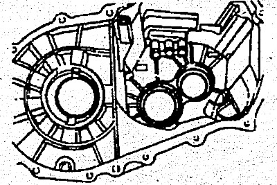
6. Install the differential assembly.
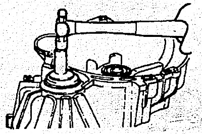
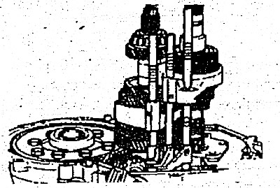
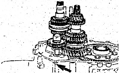
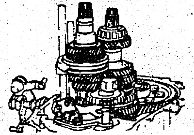
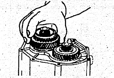
7. Install the drive shaft and secondary shaft assemblies at the same time.
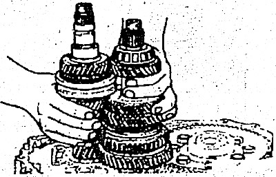
8. Install the bearing retainer.
9. Reinstall the shift rod assemblies.
- 1) Set the synchronizer sleeve of the first and second gears in neutral position.
- 2) Set the third and fourth gear synchronizer sleeve in neutral position.
- 3) Install the shift rod assemblies and fork.
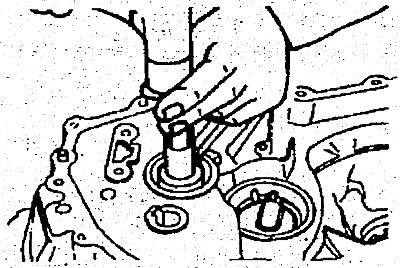
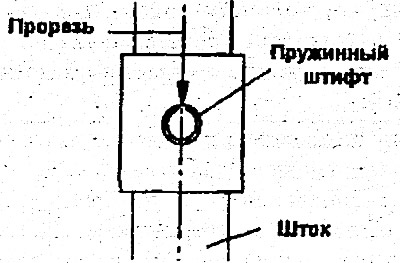
10. Installing the spring pin.
- 1) Install the spring pins using a special tool (09414-11100) or a beard with a thin cylindrical end.
- 2) When installing, make sure that the slot of the new spring pin is aligned with the center line of the rod.
11. Install the rear code gear.
12. Install the reverse lever.
13. Using a special tool (09431-21200) install a new input shaft oil seal into the transmission housing.
Warning: The oil seal is not reusable.
14. Install the secondary shaft bearing outer race and spacer sleeve using tools (09500-11000, 09432-22100A).
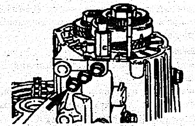
15. Installing the spacer ring.
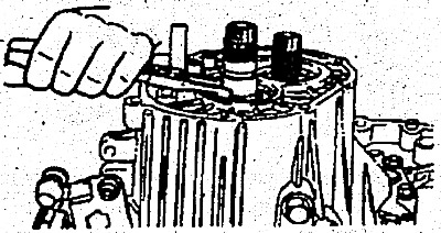
- 1) Install two pieces of 3mm diameter solder onto the outer ring of the bearing as shown in the figure.
- 2) Temporarily install the gearbox housing and tighten the bolts to the specified tightening torque, then remove the housing.
- 3) Remove the flattened pieces of solder.
- 4) Measure the thickness of the flattened solder. Select and install appropriate spacer rings to provide standard axial clearance values (mm):
- Front bearing of the drive shaft - 0.01-0.12
- Rear bearing of the drive shaft - 0.01-0.09
- Secondary shaft rear bearing - 0.01-0.15
- Rear differential bearing - 0.05-0.17
- The gap between the teeth of the gears in the differential is 0.025-0.15
16. Install the oil guide into the gearbox housing.
17. Apply MS721-40 sealant to the mating surface of the transmission housing adjacent to the clutch housing.
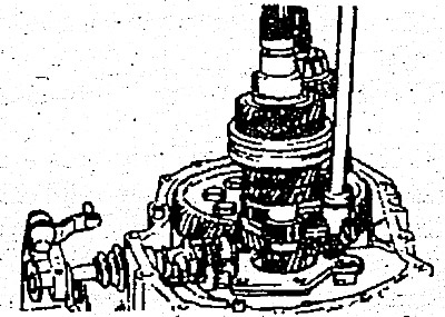
18. Install the gearbox housing onto the clutch housing and tighten the bolts.
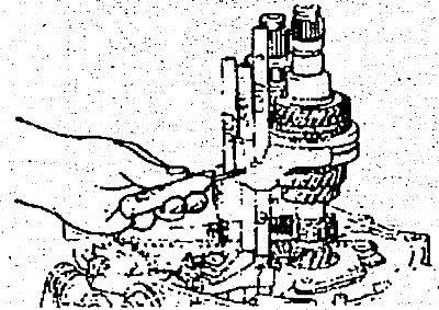
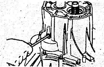
19. Use a screwdriver to center the shaft.
20. Tighten the reverse gear axle bolt to the required tightening torque (43-55 Nm).
21. Install the balls, springs and bolts with seals.
22. Using a special tool (094434-33300) install the secondary shaft gear.
23. Install the rear bearing and spacer sleeve onto the drive shaft, then install the snap ring. Install the fifth gear sleeve.
24. Install the fifth gear pinion, needle roller bearing, ring and synchronizer hub.
25. Install the fifth gear shift fork and synchronizer sleeve at the same time.
26. Installing the lock nut.
- 1) Using the shift lever and selector lever, engage first gear.
- 2) Engage the clutch with the fifth gear.
- 3) Tighten the lock nut to the required torque.
27. Using a special tool (09414-11100) or a punch with a thin cylindrical end, install the new Spring Pin, ensuring that the slot is aligned with the center line of the gearshift rod.

28. Apply MS721-40 sealant to the joint surface of the rear cover and install the cover.
29. Install the speedometer driven gear assembly.
30. Install the reversing light switch.
31. Install the mounting bracket.
32. Install the selector lever assembly.