Disassembly
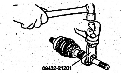
1. Using a special tool (09432-21201), remove the snap ring.
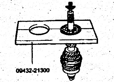
2. Using a special tool (09432-21300), remove the front bearing.
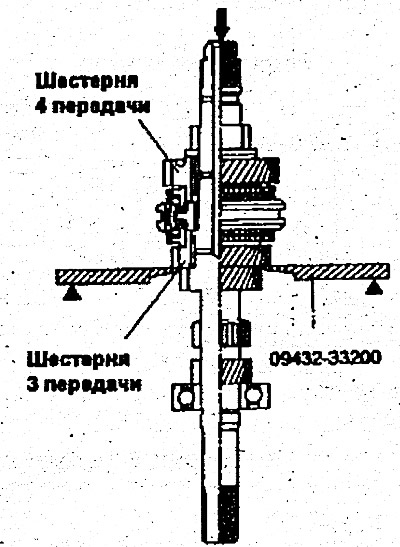
3. Using a special tool (09432-33200), remove the inner race, spacer washer, fourth gear wheel, needle bearing, bearing sleeve, synchronizer rings, hub and synchronizer sleeve of third and fourth gear wheels and third gear wheel.
[The original version is stored on the website: hyundaibook.ru]
Examination
1. Check the surface of the drive shaft at the location of the needle bearing for damage and excessive wear (area "A").
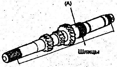
2. Check the splines for damage and wear.
Needle bearing
1. Assemble the needle bearing with the shaft or bearing sleeve and gear and make sure they rotate smoothly without excessive noise or play.
2. Check the bearing separator for deformation.
Synchronizer ring
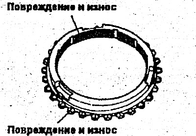
1. Check the clutch teeth for damage or breakage.
2. Check the inner surface for damage, wear and tear of turns.
3. Move the synchronizer ring toward the gear clutch and check the gap "A". If the gap deviates from the normal value, replace the ring.
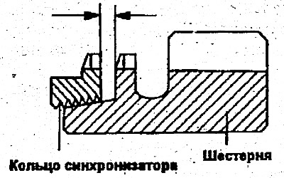
- Limit value - 0.5 mm
Synchronizer hub and clutch
1. Connect the clutch and synchronizer hub and check that they slide smoothly.
2. Check that there is no damage to the inner, front and rear surfaces of the coupling.
3. Check the wear of the end surfaces of the hub (in contact with each gear wheel).
Warning: Replace the hub and synchronizer sleeve as a set.
Cracker and synchronizer spring
1. Check the wear of the central protrusion of the synchronizer cracker.
2. Check the spring for weakening, deformation and breakage.
Gear wheels
1. Check the helical gear and coupling teeth for damage and wear.
2.. Check the synchronizing cone for surface roughness, damage and wear.
3. Check the inner, front and rear surfaces of the gear for damage and wear.
Assembly
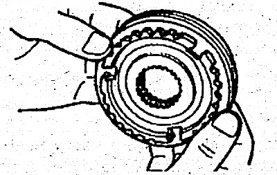
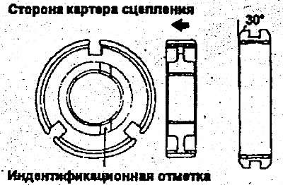
1. Assemble the hub and synchronizer sleeve so that they are positioned as shown in the figure.
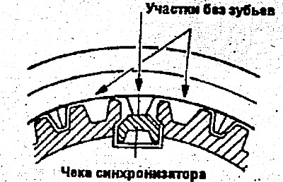
2. There are missing teeth in six places around the circumference of the synchronizer sleeve. Install the sleeve on the hub so that the tooth located between the two corresponding teeth touches the synchronizer cracker.
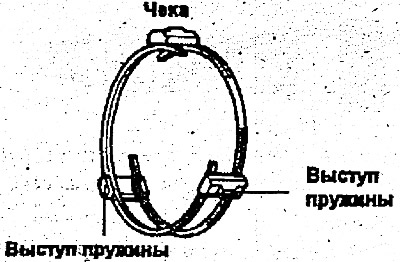
3. Install the synchronizer springs so that their protrusions rest on the grooves of the synchronizer crackers.
Caution: When installing the synchronizer springs, make sure that the front and rear springs are not positioned in the same direction.
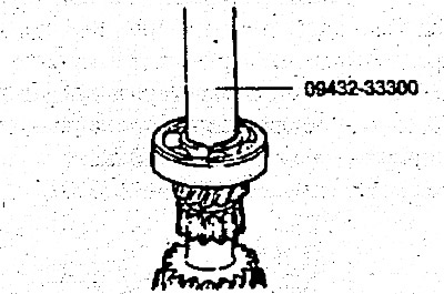
4. Using a special Tool (09432-33300), install the synchronizer of the third and fourth gears on the drive shaft.
Warnings:
1. When installing the synchronizer, make sure that the three synchronizer crackers are correctly positioned in the corresponding cutouts of the synchronizer ring.
2. After installing the synchronizer, check the smooth rotation of the third gear wheel.
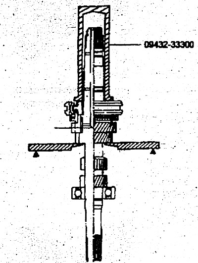
5. Using a special tool (09432-33300), install the ball bearing.
6. Install the needle bearing and fourth gear onto the drive shaft.
7. Install the ring and spacer sleeve onto the drive shaft.
- 1) Using a special tool (09432-33300) install the ball bearing.
- 2) Install the spring retaining ring.