
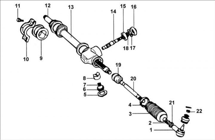
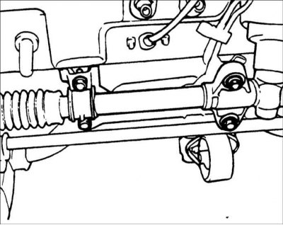
1 – steering rod end; 2 – clamp; 3 – corrugated protective cover; 4 – clamp; 5 – lock nut, 50–70 Nm; 6 – cork; 7 – spring; 8 – emphasis; 9 – rubber support; 10 – bracket; 11 – bolt, 12 – toothed rack; 13 – steering gear; 14 – steering gear shaft; 15 – gear; 16 – sealing ring; 17 – bearing; 18 – retaining ring; 19 – joint, 80–100 N·m; 20 – steering rod; 21 – lock nut, 50–55 Nm; 22 – nut, 16–34 Nm.
Removal
1. Remove the front wheel.
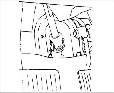
2. Remove the bolt connecting the universal joint and the steering gear shaft.
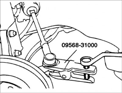
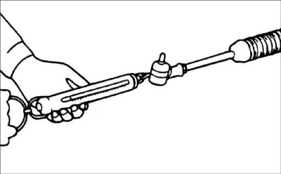
3. Remove the cotter pins and unscrew the nuts securing the ball joint pins of the steering rod ends to the steering knuckles. Use puller 09568–31000 to push the ball joint pins of the steering rod ends off the steering knuckles.
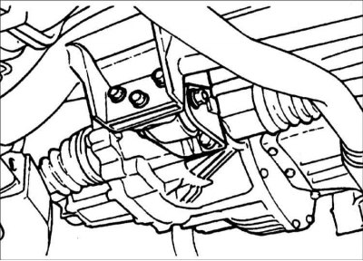
4. Remove the rear engine mount.
5. Remove the bolts and steering gear mounting brackets.
6. Move the steering gear and remove it from the right side of the car.
Disassembly
Before disassembling, measure the torque required to turn the steering gear shaft in the middle position of the toothed rack.
1. Clean the steering gear and secure it in a vice with soft jaws.
Warning: When securing the steering gear in a vice, wrap the steering gear in a cloth and be careful not to damage it when the vice is tightened.
2. Remove the steering rod.
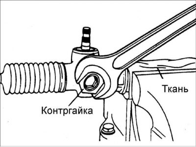
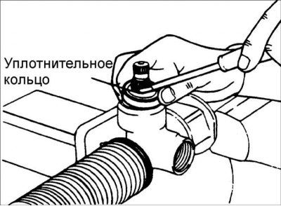
3. Unscrew the plug lock nut.
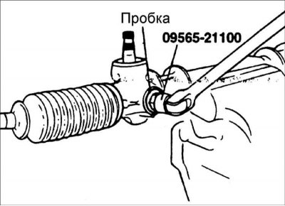
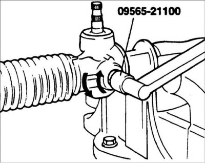
4. Using special tool 09565–21100, remove the plug.
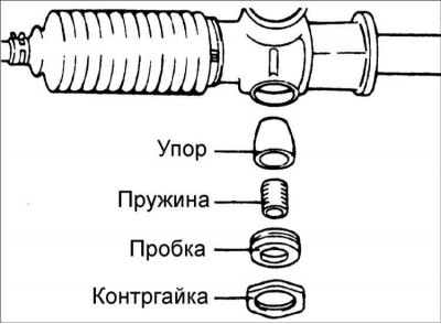
5. Remove the spring, rubber gasket and stop.
6. Remove the protective cover.
7. Remove the sealing ring from the steering gear housing.
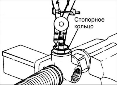
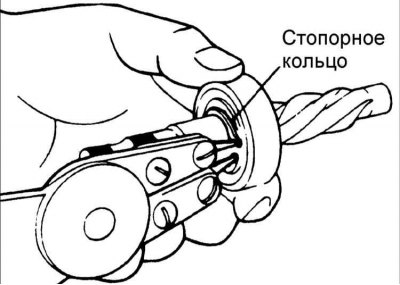
8. Remove the retaining ring from the steering gear housing and remove the gear together with the bearing.

9. Remove the bearing cap retaining ring from the gear.
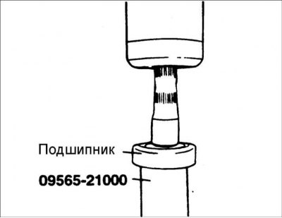
10. Using special tool 09565–21000, remove the bearing from the gear.
11. Remove the protective cover.
12. Using a chisel, unscrew the right steering rod mounting nut.
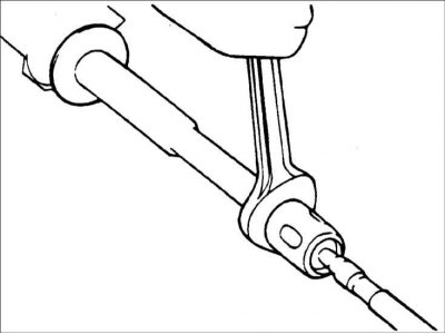
13. Move the toothed rack completely to the transmission housing and secure the toothed rack in a vice with the jaws covered with soft material. Loosen the fastening and remove the steering rod from the steering gear.
14. Remove the rack from the steering gear housing after removing the pinion.
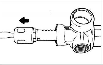
Warning! To avoid damaging the rack teeth, remove the rack from the left side.
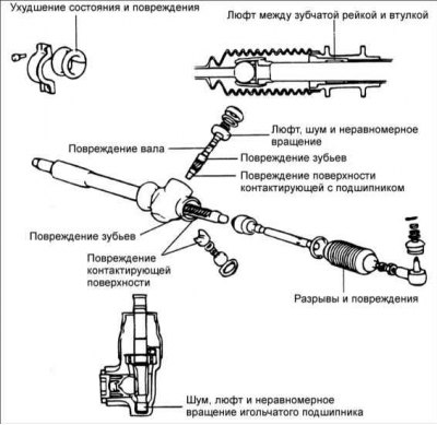
Examination
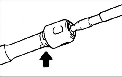
Check the steering gear components in the locations shown in the figure.
Assembly
1. Before assembly, wash all parts in solvent.
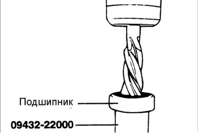
2. Using special tool 09432–22000, press the bearing into the gear.
3. Install the snap ring on the gear.
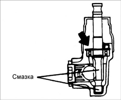
4. Lubricate the rack, pinion, bushing, bearing and other sliding surfaces.
Recommended lubricant: SAE J310a, NLGI No.2
Warning! Do not block the air passage in the crankcase bushing with lubricant.
5. After installing the rack into the steering gear housing, install the pinion in the hole, aligning it with the rack.
Warning: Make sure the rack is inserted into the steering gear housing on the left side.
Warning: Wipe off excess grease.
6. Select and install the appropriate type of snap ring to minimize axial play in the gear.
7. Before installing the sealing ring, lubricate its working edge.
Warning: A new sealing ring must be used during installation.
8. Install the stop, rubber gasket and spring.
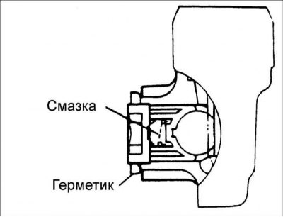
Warning: Lubricate the cup portion of the stop.
9. Using special tool 09565–21000, screw in the plug.
Tighten the plug to a torque of 11 N·m, then turn it further by an angle of 30°–60°. Secure the plug in place with a lock nut.
Locknut tightening torque: 50–70 Nm
Warning! Adjust the position of the plug with the steering gear in neutral position.
Warning: Apply a bead of sealant between the lock nut and the steering gear housing.
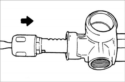
10. Install the tie rod end and protective boot. Secure the boot with new clamps.
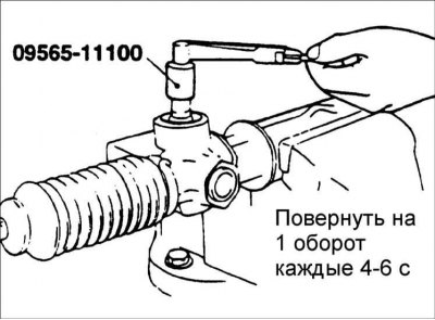
11. Measure the preload with the protective boot and lubricant by turning the pinion with the special tool 09565-11100 one revolution every 4-6 s. Also measure the starting force of the toothed rack.
Total gear preload:
- ±180° or less from neutral position: 0.4–1.1 N·m
- ±180° or more from neutral position: 0.3–1.6 N·m
- Starting force of toothed rack: 50–300 N
Warning! Pinion preload must be measured over the entire length of the steering gear stroke.
 |
 |
Installation
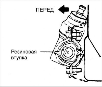
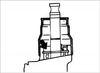
1. Install the rubber bushing on the steering gear as shown in the figure.
2. Install the pinion gear into the mesh and the steering gear and pinion assembly to the crossmember.
Warning! Make sure that the steering gear and pinion are not warped or damaged when installing. Be careful not to over-tighten the connections, as this will warp the steering gear and pinion and increase steering effort.
3. Tighten the connecting bolt.
Tightening torque: 15–20 Nm
4. Secure the steering rods to the steering knuckle.
Tightening torque of the steering rod ball joint nut: 16–34 N·m
Warning: Align the groove of the nut with the hole for the cotter pin and tighten the nut to the specified torque.
5. Adjust the wheel alignment angles.
6. Make sure the protective cover is not twisted and secure it with a clamp.