
Removal
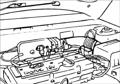
1. Remove the air intake pipe.
2. Remove the clamps securing the pressure and return hoses to the steering gear housing.
3. Drain the fluid from the power steering hydraulic drive.
4. Disconnect the pressure and return hoses from the steering gear housing.
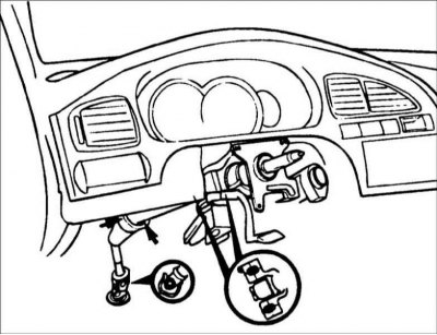
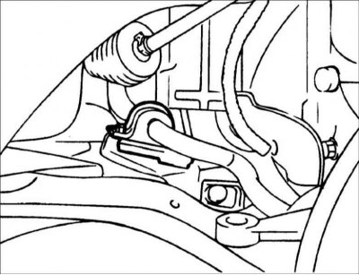
5. Remove the bolt connecting the universal joint and the steering gear shaft.
6. Remove the bracket, dust cover and dust cover mounting plate.
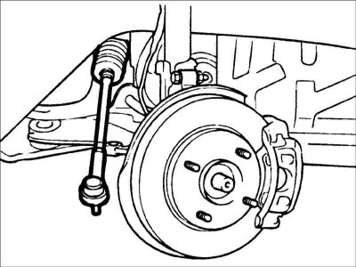
7. Raise the car.
8. Remove the front wheels.
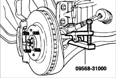
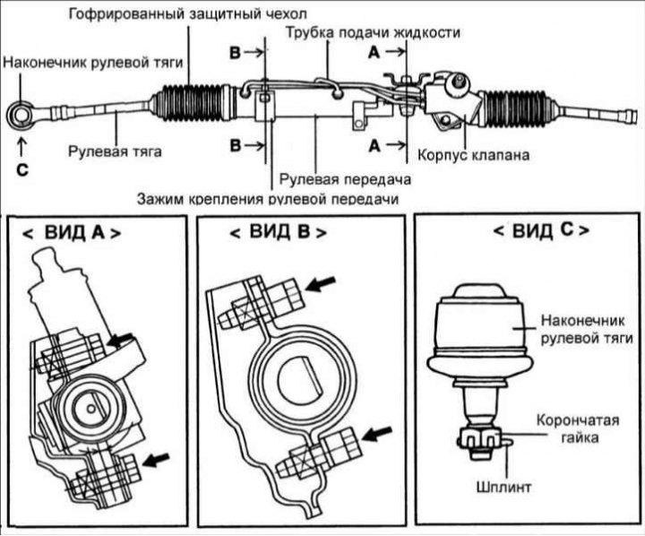
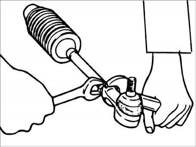
9. Remove the cotter pins and unscrew the nuts securing the ball joint pins of the steering rod ends to the steering knuckles. Using puller 09568–31000, press the ball joint journals of the steering rod ends out of the steering knuckles.
10. Remove the right anti-roll bar mounting bracket.
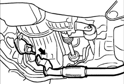
11. Disconnect the front muffler.
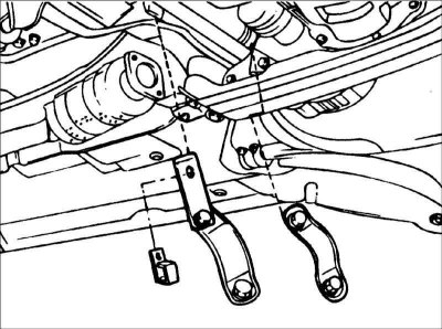
12. Unscrew the bolts and remove the clamps securing the steering gear and the pressure and return pipes.
13. Move the steering gear and remove it from the right side of the car.
Warning: When removing the steering gear, be careful not to damage the protective boots.
Checking and preliminary adjustment before installation
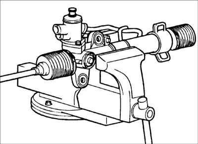
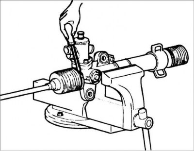
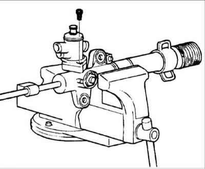
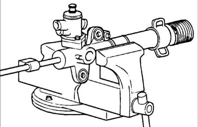
Secure the steering gear in a vice with jaws covered with soft material.
Warning: When securing the steering gear in a vice, wrap the steering gear in a cloth and be careful not to damage it when the vice is tightened.
Gear preload
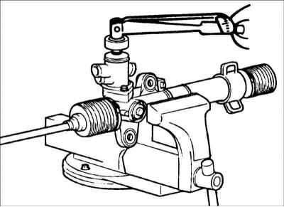
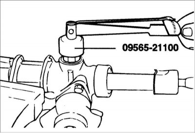
1. Measure the preload by turning the pinion with the special tool 09565-11100 one revolution every 4-6 s. Also measure the starting force of the toothed rack. Total gear preload: 0.6–1.3 Nm.
Warning: Measure the preload over the full stroke of the rack.
2. If the preload is not within the required value, first adjust the tightening torque of the plug and recheck the preload of the gear.
3. If adjusting the plug tightening torque does not produce positive results, check or replace the plug components.
Steering traction resistance
1. Perform 10 steering rod deflections.
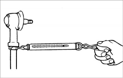
2. Use a dynamometer to measure the force required to move the steering rod. Steering rod deflection force: 8–22 N.
3. If the measured value exceeds the standard value, replace the steering tie rod assembly.
Caution! If the measured value is below the nominal value and the steering rod turns smoothly and without play, it can be installed on the vehicle. However, if the measured value is below 4.3 N, replace the tie rod.
Checking the corrugated protective cover
1. Visually inspect the corrugated protective cover for damage and deterioration of its properties.
2. Make sure the protective cover is installed in the correct position.
3. If the corrugated protective cover has defects, replace it.
Disassembly
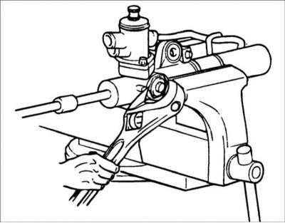
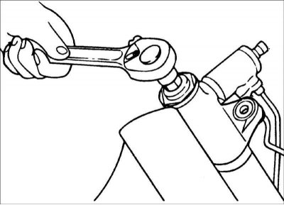
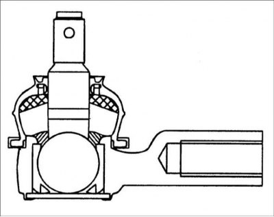
1. Remove the tie rod end from the tie rod.
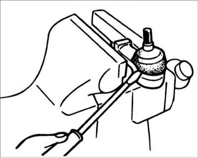
2. Using a screwdriver blade, remove the protective cover of the ball joint of the tie rod end.
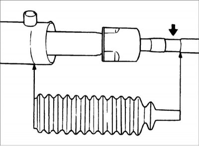
3. Remove the tape clamp securing the corrugated protective cover.
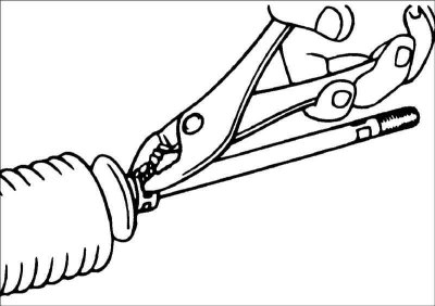
4. Remove the clamp securing the corrugated protective cover.
5. Move the corrugated protective cover to the steering rod.
Caution: When replacing the corrugated protective cover, check the steering gear for rust.
6. Remove the guide tube from the gear housing.
7. While slowly moving the toothed rack, drain the fluid from the steering gear housing.
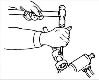
8. Use a chisel to remove the lock washer securing the steering rod to the toothed rack.
9. Remove the steering rod from the toothed rack.
Warning: When removing the steering rod, be careful not to turn the toothed rack.
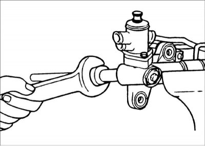
10. Unscrew the lock nut securing the plug.
11. Using a 14 mm wrench, remove the plug from the base of the steering gear.
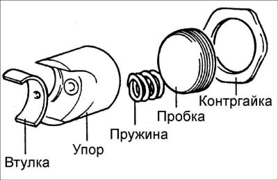
12. Remove the spring, stop and bushing from the steering gear housing.
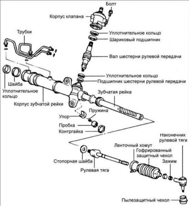
13. Remove the two bolts and remove the valve body.
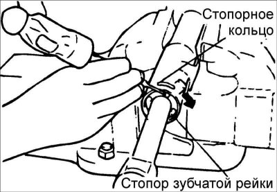
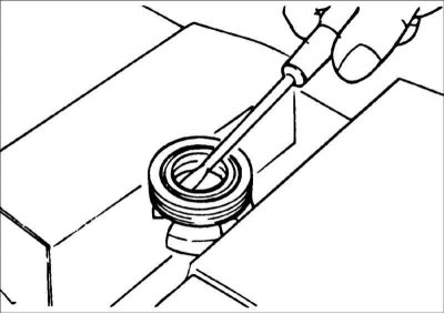
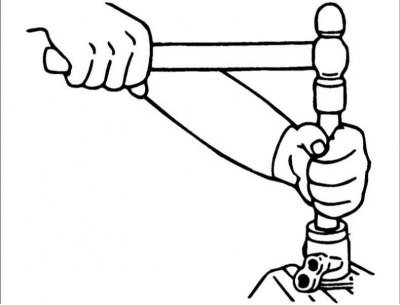
14. Using a screwdriver blade, turn the rack stopper clockwise until the end of the locking ring comes out of the groove in the steering gear housing.
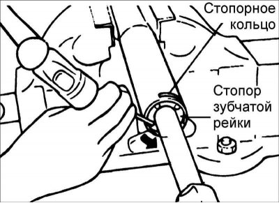
15. When the end of the locking ring comes out of the hole in the rack cylinder housing, use a screwdriver blade to turn the steering gear stopper counterclockwise and remove the locking ring.
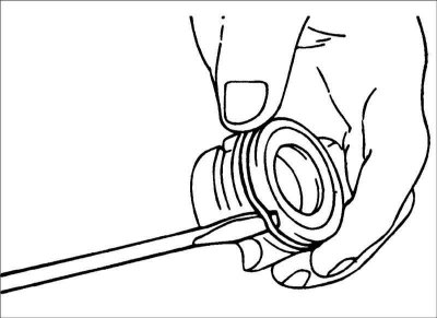
16. Remove the O-ring from the rack bushing.
17. Remove the oil seal ring from the rack bushing.
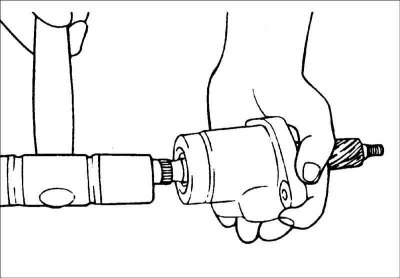
18. Using a plastic hammer, knock the valve body out of the casing.
19. Using special tool 09565-21000, remove the oil seal and ball bearing from the valve body.
20. Remove the ball bearing from the steering gear housing.
Warning: Be careful not to damage the valve cylinder in the steering gear housing.
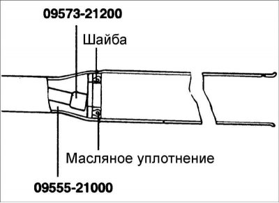
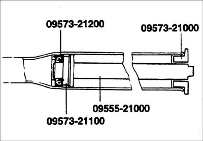
21. Using special tools 09573–21200, 09555–21000, remove the oil seal from the steering gear housing.
Warning: Be careful not to damage the rack cylinder in the steering gear housing.
Checking the toothed rack
1. Check the rack for damaged or worn teeth.
2. Check the oil seal contact surfaces for damage.
3. Check the rack for deflection or twisting.
4. Check the O-ring for any damage or wear.
5. Check the oil seal for damage or wear.
Checking the valve gear
1. Check the valve gear for damage to the teeth or wear.
2. Check the oil seal contact surfaces for damage.
3. Check the sealing ring for damage or wear.
4. Check the oil seal for damage or wear.
Checking the bearing
1. Check the bearing for jamming or extraneous noise when rotating.
2. Check the bearing for excessive play.
3. Check for missing needle bearing.
Other checks
1. Check the surface of the steering gear housing cylinder for damage.
2. Check the protective cover for damage, aging and cracks.
Assembly
1. Lubricate the sliding surface of the rack oil seal. Recommended lubricant: PSF–3.
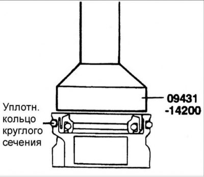
2. Install the return washer and oil seal into the steering gear housing in the position shown in the figure.
3. Lubricate the sliding surface of the rack bushing oil seal. Recommended lubricant: PSF–3.
4. Install the oil seal into the steering gear bushing.
5. Lubricate the O-ring and install it into the rack bushing.
6. Lubricate the rack teeth. Recommended grease: SAE J310, NLGI No. 2.
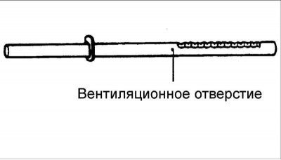
Warning: Do not block the ventilation hole in the rack with grease.
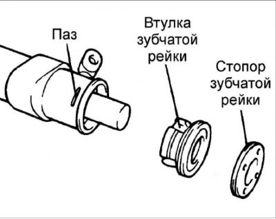
7. Install the toothed rack into the steering gear housing. Then install the bushing and rack stop.
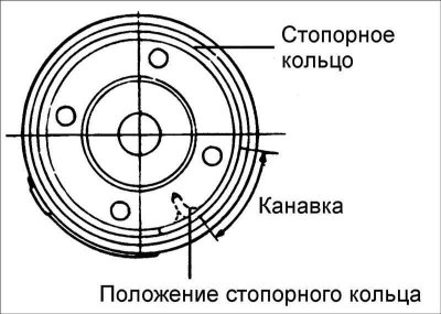
8. Press the rack stopper until a groove appears and, turning the stopper, install the retaining ring.
Warning! The retaining ring must not be visible through the hole in the rack housing.
9. Using the special tool, install the oil seal and ball bearing into the valve body.
10. Lubricate the valve assembly with oil and recommended lubricant and install it into the steering gear housing.
11. Lubricate with oil and install the seal into the valve body using a special tool. Install the valve body assembly with the O-ring into the steering gear housing.
12. Install the lock washer and steering rod and countersink the washer flange in two places.
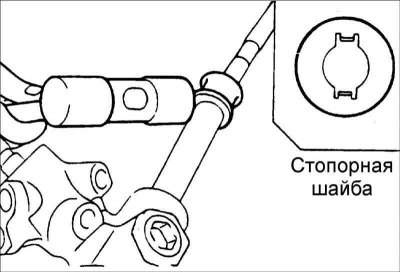
- 1. Align the tabs of the lock washer with the recesses on the steering gear housing.
- 2. Always use a new lock washer.

13. Install the bushing, stop and spring in the order shown in the figure. Before installation, apply sealant to the threaded portion of the plug.
14. Set the rack to the center position and install the bushing, stop and spring. Before installation, apply sealant to the threaded portion of the plug. Using a special tool, tighten the plug to a tightening torque of 15 N·m. Loosen the cap by 30–60° and tighten the lock nut to the required tightening torque. Tightening torque: 50–70 Nm.
15. Tighten the guide tube to the required tightening torque and install the rubber element with glue.
16. Apply grease to the bellows boot and install it into the groove of the steering rod. Recommended lubricant: silicone grease.
17. Secure the corrugated protective cover with a new clamp.
18. Check that the corrugated protective cover is not twisted.
19. Fill the protective boot with lubricant, install it on the ball joint of the tie rod end and secure it with a snap ring.
Recommended material:
- A: POLY LUB GLY 801 KB or equivalent
- B: SHOWA SUNLIGHT MB2 or equivalent
- Protective case: THREE BOND
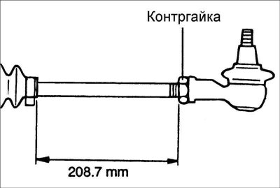
20. Install the steering rods so that the length of the left and right steering rods is the same. Length of steering rods: 204.5 mm.
21. Check the gear preload.
Installation

1. Install the steering gear on the right side of the vehicle.
2. Install the dust cover and plate.
3. Secure the dust cover and plate with a new clamp.
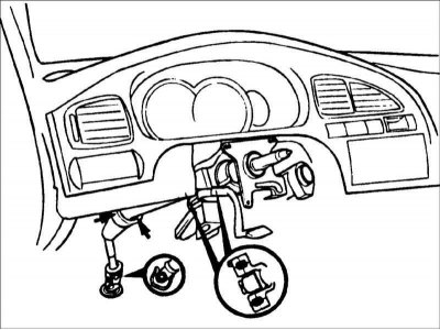
4. Connect the steering gear shaft to the steering shaft.
5. Further installation is carried out in the reverse order of removal.
6. Bleed the power steering hydraulic drive.