
Contents: Pistons and cylinders ⇓ Crankshaft ⇓
Pistons and cylinders
In the upper third of each piston, three piston rings are placed in corresponding grooves. Under the action of spring forces, they are pressed against the cylinder wall. Both upper piston rings block the path of gases from the combustion chamber down into the engine crankcase, while the lower oil scraper ring prevents oil from getting from the engine crankcase into the combustion chamber.
The cylinder in which the piston moves up and down is made in the engine block from gray cast iron. Cylinder bores are honed (polished) crosswise. The walls should not be completely smooth, because otherwise the oil needed to lubricate the cylinder will not be able to stay on them. The cylinder bores are 0.03 mm larger than the corresponding pistons. During engine repair, cylinders can be reground up to three times.
Crankshaft
The task of the crankshaft is to convert the reciprocating motion of the pistons in the cylinders into rotational motion. The individual knees (cranks) are located at certain angles to each other. In the engines under consideration they are located at an angle of 180°, i.e. they stand opposite each other. To ensure vibration-free operation, counterweights are located at opposite ends of the crankshaft journals.
To avoid bending of the crankshaft during operation, it rests on 5 main bearings in the engine block. Each crank with connecting rod on the left and right is "supported" by main bearings.
At the rear of the crankshaft in relation to the direction of travel is a disk with a toothed ring for the starter pinion. This is either a flywheel, on which the clutch is fixed and, thus, the connection with the gearbox (gearbox) or a drive disk on the torque converter of an automatic gearbox. At the other end of the crankshaft, a toothed wheel is screwed to drive the toothed belt and a pulley for the V-belt(s).
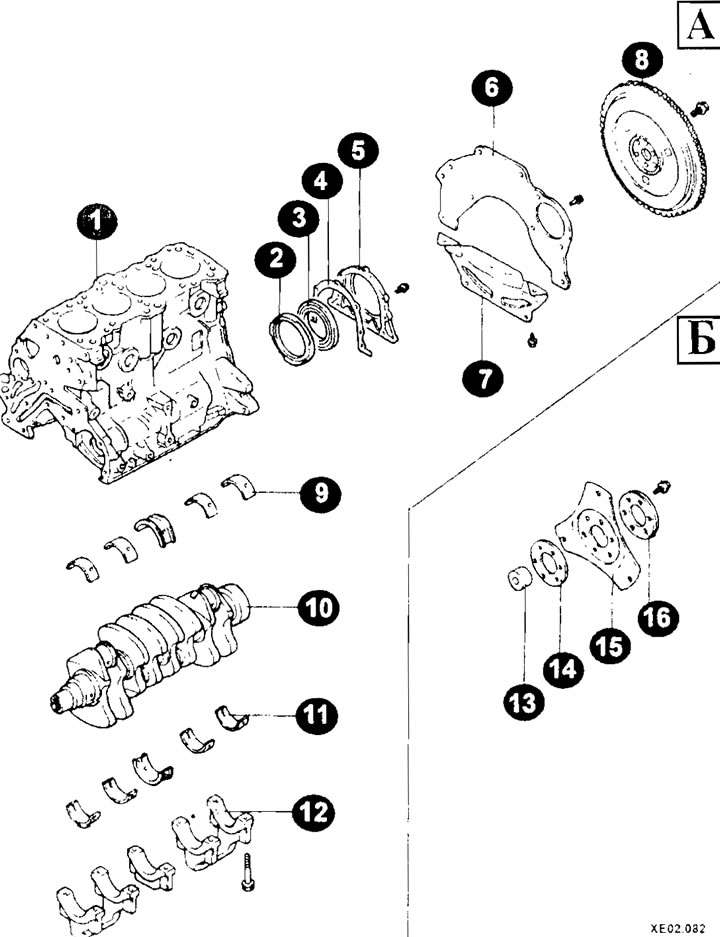
Cylinder block elements of 1.6 and 1.8 liter engines
A - models with manual transmission;
B - models with automatic transmission;
1 — cylinder block;
2 - oil separator;
3 — oil seal;
4 - gasket;
5 - back cover;
6 - plate;
7 — casing;
8 — flywheel;
9, 11 — inserts (main bearings) crankshaft;
10 — crankshaft;
12 — main bearing caps;
13 — bushing;
14, 16 - adapter plate;
15 — drive plate.
Note: The installation elements of the cylinder block of the 2.0 liter engine are made similarly.
Four connecting rods with replaceable bearing liners are installed on the connecting rod journals of the crankshaft. At the other end are bronze bushings for the piston pins, which are made "floating". The pistons and piston pins can therefore move slightly back and forth on the connecting rod.
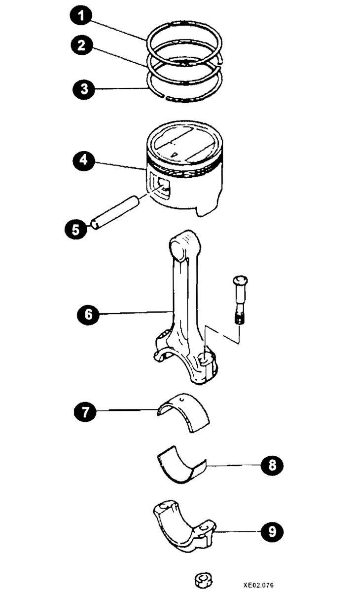
Elements of the crank mechanism
1 - upper piston ring;
2 - lower piston ring;
3 - oil scraper ring;
4 — piston;
5 - piston pin;
6 — connecting rod;
7, 8 — connecting rod bearing shell;
9 — connecting rod cover.