
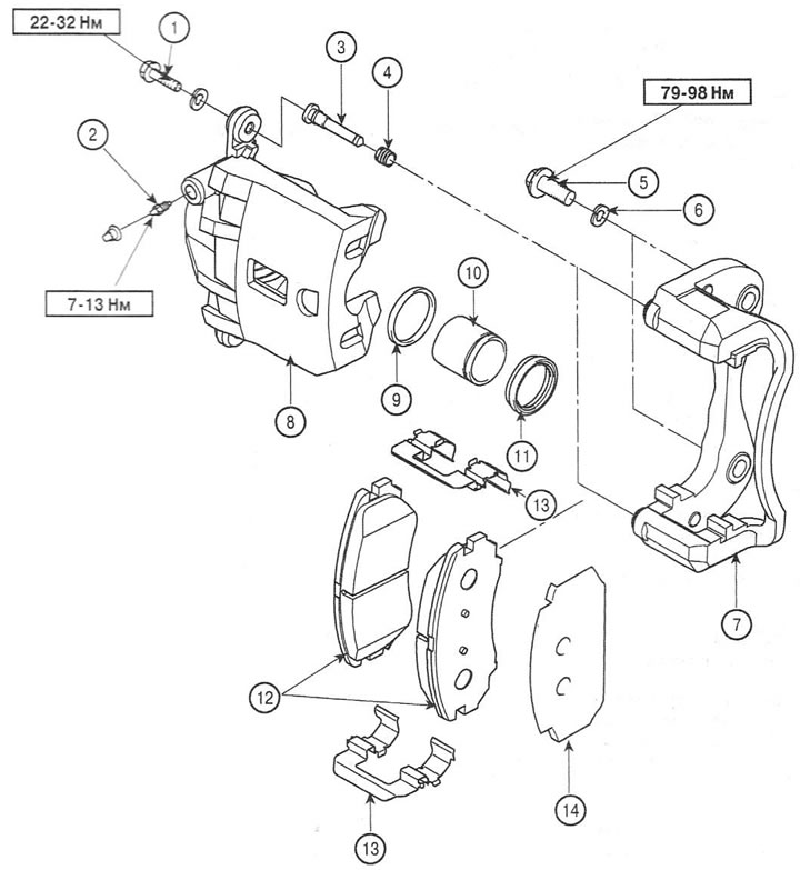
1. Screw; 2. Air bleed valve; 3. Guide pin; 4. Dust cover; 5. Screw; 6. Washer; 7. Caliper bracket; 8. Brake caliper; 9. Seal; 10. Piston; 11. Piston dust cover; 12. Brake shoe; 13. Retainer; 14. Anti-friction lining
Removal
1. Remove the front wheel. Tightening torque of the nuts: 90-110 Nm.
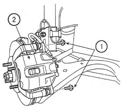
2. Remove the guide pin screws (1) and lift the brake caliper (2) up. Check the dust boots and brake hose for damage.
Note: If it is necessary to remove the brake caliper, disconnect the brake hose.
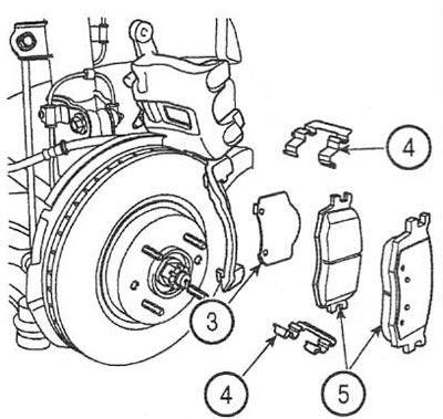
3. Remove the anti-friction lining (3), clamps (4) and brake pads (5).
4. Remove the screws and caliper bracket.
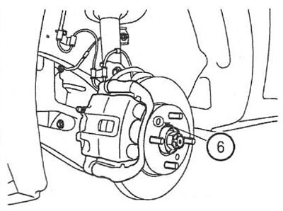
5. Remove the brake disc from the hub. If the disc is stuck to the hub due to overheating or corrosion, screw an M8 screw into the hole (6) to remove it.
Note: When removing the disc, do not use a hammer to avoid damaging the hub or disc.
Examination
Brake DISC 4
6. Clean the surface of the brake disc and measure its thickness at 4 equally spaced points. Nominal value: 22.0 mm. Minimum allowable value: 20.0 mm. The difference between all measured values should not exceed 0.05 mm. If the measured value is less than the limit, replace the brake disc.
Note: The brake disc and pads are replaced as a set on both sides.
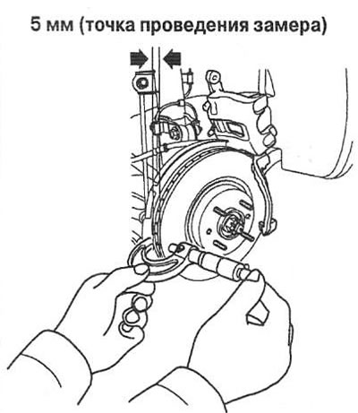
7. Set the dial indicator approximately 5mm from the edge of the disc and check its runout. Nominal value: less than 0.03mm.
8. If the runout value is greater than the nominal value, replace the hub with the disc and recheck the runout.
Note: Before removing the disc, mark the stud on the side with the greatest runout with chalk.
9. If the runout does not exceed the nominal value, rotate the brake disc 180° relative to the mark, install the disc and recheck the runout.
10. If it is not possible to correct the runout value by changing the position of the disc, replace the brake disc.
Brake pads
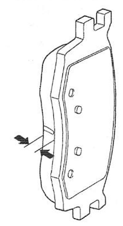
11. Check the wear of the friction lining. Nominal value: 11.0 mm. Minimum allowable value: 2.0 mm. If the measured value is less than the limit, replace the brake pads.
12. Check for traces of oil and grease on the surfaces of the brake pads.
Installation
13. Install the brake disc and caliper bracket. Tightening torque of screws: 78-96 Nm
14. Install the retainers, anti-friction lining and brake pads into the caliper bracket.
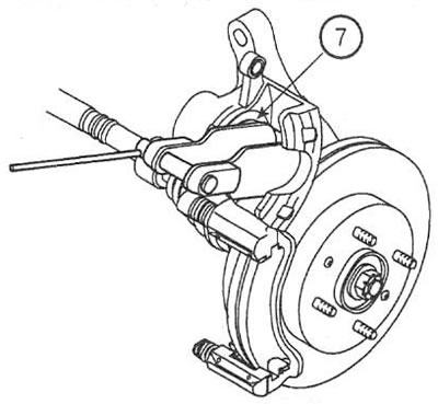
15. Using a suitable tool, press the piston (7) into the caliper to install the pad.
16. Lower the caliper down. Be careful not to damage the finger dust boots. Install and tighten the guide finger screws. Tightening torque: 22-32 Nm.
Note: If the caliper was removed, reconnect the brake hose.
17. Bleed the brake hydraulic system and check for leaks.