
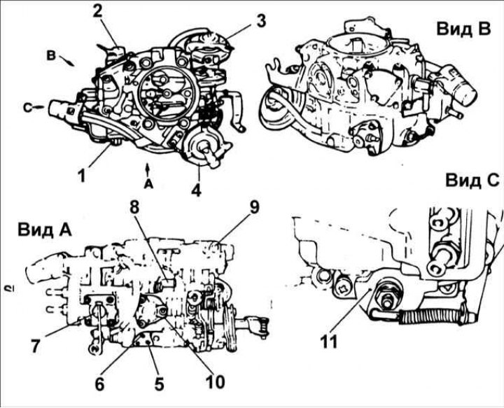
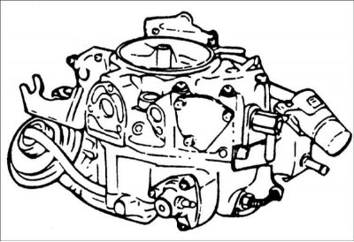
1 – accelerator pump; 2 – auxiliary accelerator pump; 3 – vacuum chamber; 4 – starting device; 5 – vacuum pipe; 6 – vacuum pipe of the ignition distributor; 7 – accelerator pump; 8 – electromagnetic valve of forced idle speed; 9 – launcher chamber; 10 – exhaust gas re-burning system valve; 11 – throttle position sensor.
Carburetor Components
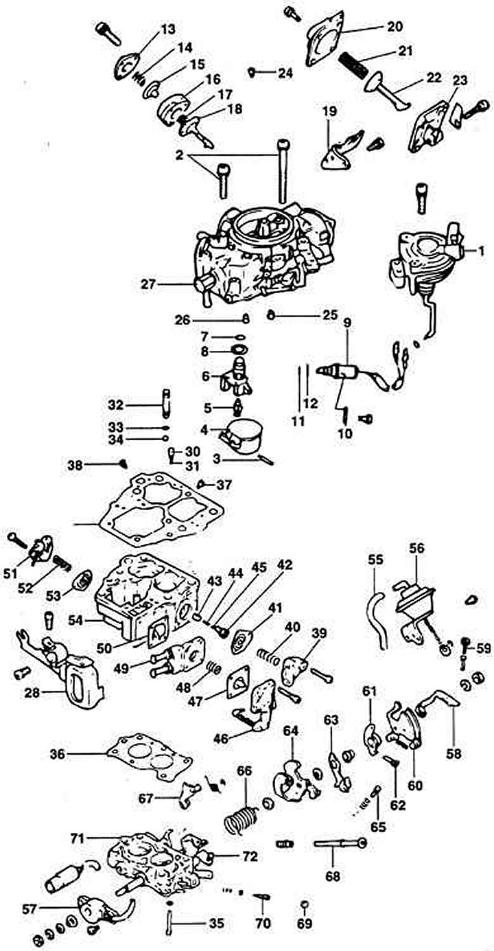
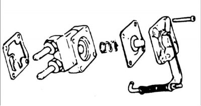
1 – starting device; 2 – screw; 3 – hairpin; 4 – float; 5 – needle valve; 6 – needle valve seat; 7 – sealing ring; 8 – nest; 9 – holder; 10 – Slow Speed Control Valve (SCSV); 11 – sealing ring; 12 – sealing ring; 13 – lid; 14 – spring; 15 – diaphragm; 16 – body; 17 – spring; 18 – diaphragm; 19 – bracket; 20 – lid; 21 – spring; 22 – diaphragm; 23 – body; 24 – main air jet; 25 – primary idle fuel jet; 26 – secondary idle fuel jet; 27 – float chamber cover; 28 – bracket; 29 – float chamber cover gasket; 30 – weight; 31 – ball; 32 – cork; 33 – sealing ring; 34 – ball; 35 – screw; 36 – gasket; 37 – primary main jet; 38 – secondary main jet; 39 – cover; 40 – spring; 41 – diaphragm; 42 – fuel mixture enrichment valve; 43 – fuel mixture enrichment tube; 44 – spring; 45 - ball; 46 – accelerator pump cover; 47 – diaphragm; 48 – spring; 49 – body; 50 – gasket; 51 – cover; 52 – spring; 53 – diaphragm; 54 – housing with mixing chambers; 55 – vacuum hose; 56 – vacuum chamber; 58 – lever; 59 – adjusting screw; 60 – throttle lever; 61 – valve tappet; 62 – idle speed adjustment screw; 63 – free lever; 64 – support plate; 65 – idle speed adjustment screw (SAS–2); 66 – spring; 67 – secondary lever; 68 – idle speed adjustment screw (SAS–1); 69 – cork; 70 – fuel mixture quality adjustment screw (MAS); 71 – carburetor body; 72 – idle speed adjustment screw (SAS–3).
Removal
1. Disconnect the cable from the negative battery terminal.
2. Drain the coolant to a level below the intake manifold.
3. Remove the carburetor cover.
4. Disconnect the accelerator cable from the throttle lever.
5. Disconnect the vacuum hoses from the carburetor.
6. Disconnect the connector from the positive idle speed solenoid valve.
7. Place a container under the fuel hose connections to catch any leaking fuel and disconnect the fuel supply hoses from the carburetor fittings.
8. Remove the bolts and remove the carburetor from the engine.
Disassembly
Warning: Do not remove the choke or throttle valves.
1. On a carburetor with an automatic choke, remove the coolant hose from the carburetor body pipe.
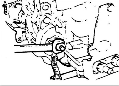
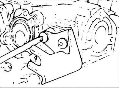
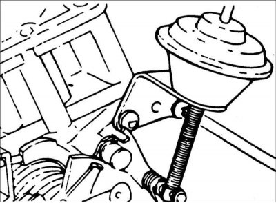
2. Remove the starting rod from the free lever.
3. Remove the bracket with the connector.
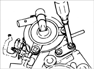
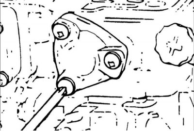
4. Remove the starting device.
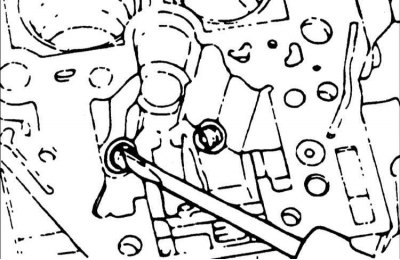
5. Remove the accelerator pump rod from the throttle lever.
6. Remove the float chamber cover, unscrew screw "B" and remove the carburetor body.
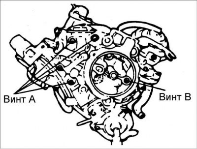
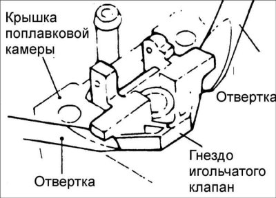
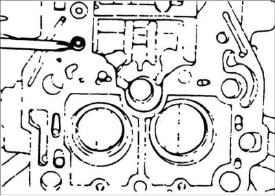
7. Remove screws "A" and remove the float chamber cover from the main body.
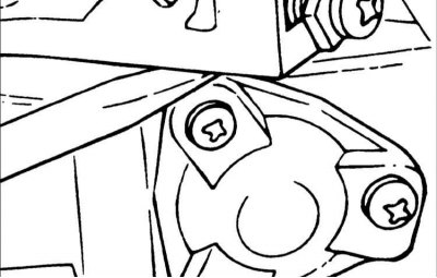
8. To remove the float chamber cover, insert the blade of a flat-blade screwdriver between the cover and the main body and, using the screwdriver as a lever, slowly pry the cover off.
Warning: Do not use excessive force when removing the cover.
9. Remove the pin and then remove the float and needle valve.
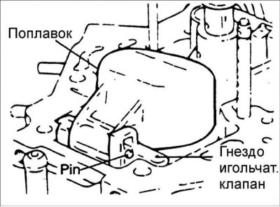
Warning! Don't drop the float.
Warning: Be careful not to damage the needle valve.
10. Using a flat-head screwdriver, lever out the needle valve seat.
Warning: When removing the needle valve seat, be careful not to damage the float chamber.
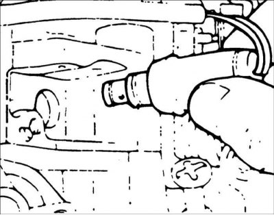
11. Remove the holder and the positive idle speed solenoid valve.
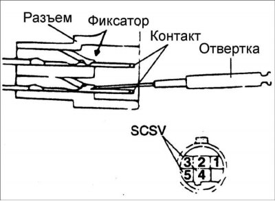
12. Using a thin-bladed screwdriver, press the tabs and remove the two contacts from the positive idle speed solenoid valve connector.
13. Remove the accelerator cable support bracket.
14. Remove the idle jets and main air jet.
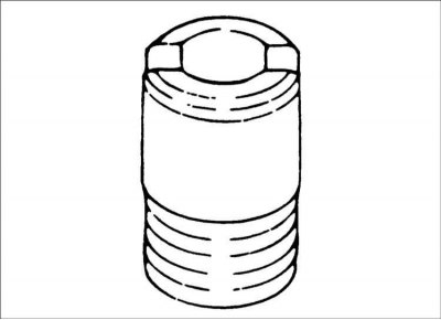
Warning: To remove the jets, use a thin-bladed screwdriver and work carefully so as not to damage the jets.
15. Remove the accelerator pump and inspect the ball and weight.
Warning! Do not turn the housing with the mixing chambers upside down to remove the accelerator pump. Check the ball and weight through the holes in the gasket.
16. Separate the float chamber from the carburetor body.
17. Remove the main jets.
Warning: To remove the jets, use a thin-bladed screwdriver and work carefully so as not to damage the jets.
18. Remove the three screws securing the fuel mixture enrichment valve cover to the float chamber body. Remove the cover, spring and diaphragm.
19. Use a screwdriver to loosen the fuel enrichment tube and remove the spring and ball.
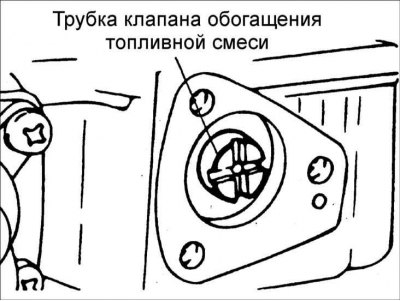
Warning! The fuel enrichment valve consists of many small parts. Do not lose them.
20. Remove the four screws securing the accelerator pump to the float chamber cover. Remove the pump cover, diaphragm, spring and gasket.
Warning! Before screwing in the accelerator pump mounting screws, apply a locking compound to their threads to prevent them from loosening.
21. Remove the E-clip and washers from the secondary throttle shaft and remove the diaphragm spring.
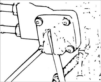
22. Remove the two screws securing the diaphragm bracket to the carburetor body and remove the throttle diaphragm.
23. Remove the auxiliary accelerator pump.
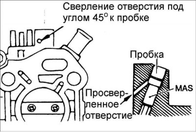
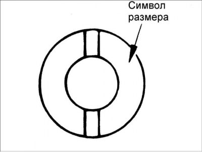
24. Drill a 2mm hole in the center hole for the fuel mixture adjustment screw (MAS), then ream the hole with a 3mm drill bit. Insert a punch into the drilled hole and knock out the plug.
Assembly
Assembly is carried out in the reverse order of disassembly, taking into account the following.
1. Clean all parts before assembly.
2. Check that the air and fuel passages are not clogged.
3. When replacing jets, the old and new jets must have the same dimensions, since jets are selected at the factory according to their performance.
4. Do not reuse O-rings or gaskets.
 |
 |
Examination
Check the condition and replace or repair the following parts if necessary.
1. Check that the air and fuel jets are not clogged. If they are, wash them in solvent and blow them out with compressed air. Do not use metal wire for cleaning.
2. Check the diaphragms for damage or cracks.
3. Make sure the needle valve moves easily. If the valve is difficult to move or sticks, repair or replace it.
4. Check the fuel inlet filter located above the needle valve for clogging.
5. Check the float movement.
6. Check the operation of the throttle valve, choke valve and rods. If they move with difficulty, wash them and lubricate their axles with clean engine oil.
7. Check the float chamber cover and carburetor body for damage or cracks.
Checking the SCSV Solenoid Valve
1. Using additional wires, supply battery voltage to the contacts of the idle speed control solenoid valve connector.
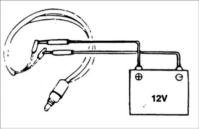
2. Make sure the valve operates with a clear click.
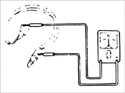
3. Use an ohmmeter to check that there is no conductivity between the connector contacts and the body of the idle speed control solenoid valve.
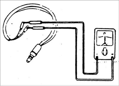
4. Use an ohmmeter to measure the resistance between the contacts of the idle speed control solenoid valve connector.
Resistance: 48-60 kOhm at 20°C
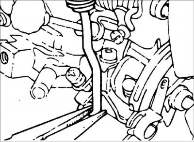
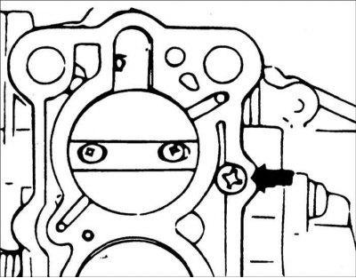
Checking the primary throttle valve opening clearance
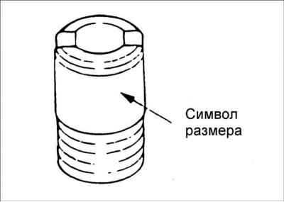
1. Using a drill bit, measure the gap between the primary chamber throttle valve and the housing.
Clearance: 0.93 mm
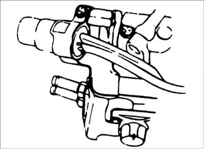
2. If the gap is not as required, adjust it by turning the adjusting screw. To increase the gap, turn the screw clockwise; to decrease the gap, turn the screw counterclockwise.
Installation
1. Check the condition and, if necessary, clean the mating surfaces of the carburetor and intake manifold.
2. Install a new carburetor gasket onto the intake manifold.
3. Carefully install the carburetor onto the intake manifold.
4. Gradually, one by one, screw in the carburetor mounting bolts so that the gasket is compressed evenly. The bolts must be tightened very securely to prevent air from being sucked in between the carburetor and the intake manifold.
5. Connect the accelerator cable, vacuum hoses and fuel hoses.
6. Check that the vacuum hoses are securely connected.
7. Check that the air damper opens and closes fully.
8. Check that the throttle valve opens fully when you press the accelerator pedal.
9. Install the air filter.
10. Connect the cable to the negative terminal of the battery.
Warning! Before the first start, do not pour fuel into the air neck of the carburetor to speed up the engine start after servicing the fuel system. To pump fuel, turn the engine crankshaft with the starter.
11. Check the idle speed and adjust it if necessary.