
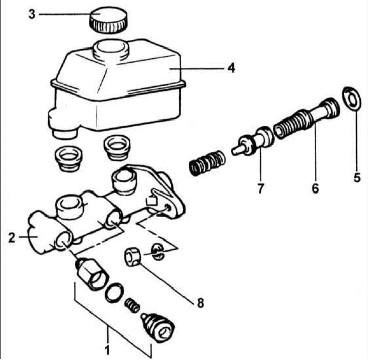
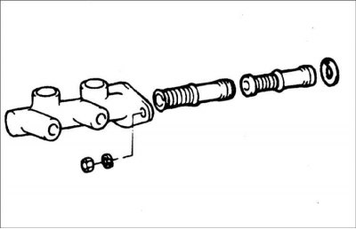
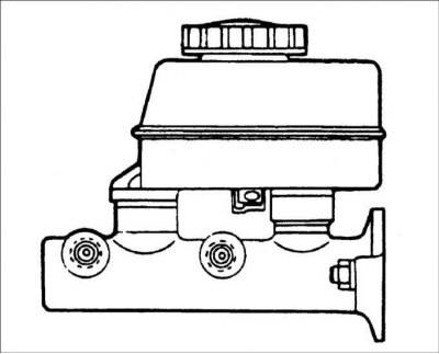
1 - pressure regulator; 2 – the main brake cylinder; 3 - plug; 4 - compensation tank; 5 - retaining ring; 6 - primary piston; 7 - secondary piston; 8 - nut, 8–12 Nm.
Withdrawal
1. Disconnect the electrical connector from the brake fluid level sensor.
2. Disconnect the brake pipes from the master brake cylinder and close the opened holes with suitable plugs.
Warning! Brake fluid dissolves paint, plastic, and wire insulation, so if you accidentally spill fluid on your vehicle's paintwork or components, wash it with plenty of water.
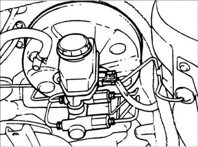
3. Disconnect the pressure regulator bracket and remove the brake master cylinder. Turn away nuts of fastening of the main brake cylinder.
Disassembly
1. Remove the cap and drain the brake fluid from the reservoir.
2. Remove the reservoir from the brake master cylinder.
Warning! If necessary, secure the brake master cylinder in a vise by gripping its main body rather than the flange.
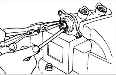
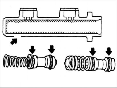
3. Remove the primary and secondary pistons from the brake master cylinder housing.
Warning! Be careful not to damage the master cylinder bore diameter.
Warning! Do not disassemble the primary and secondary pistons.
Examination
1. Check the inner surface of the brake master cylinder housing for rust and wear.
2. Check the primary and secondary pistons for rust, nicks or wear.
3. Check the primary and secondary pistons for deterioration.
Assembly
1. Lubricate the inner surface of the master cylinder and the outer surfaces of the primary and secondary pistons with the recommended brake fluid.
Recommended brake fluid: DOT3
2. Carefully insert the spring and secondary piston into the master cylinder bore.
3. Carefully insert the primary piston into the master cylinder bore.

4. Press the primary piston and install the circlip into the master cylinder bore diameter groove.
5. Install the stopper on the tank.
6. Lubricate two o-rings (inside and outside) brake fluid and insert them into the brake master cylinder housing.
Warning! O-rings must be replaced each time the tank is replaced.
7. Firmly insert the reservoir into the O-rings of the brake master cylinder.
8. Connect the electrical connector to the brake fluid level sensor.
Installation
1. Establish the main brake cylinder on the vacuum amplifier of brakes and screw two nuts. Tighten the two nuts securing the brake master cylinder.
Tightening torque: 8–12 Nm
2. Connect the two brake lines and electrical connector to the brake fluid level sensor.
Tubing Torque: 13 - 17 Nm
3. Fill with brake fluid and bleed air from the hydraulic circuit of the brake system.