
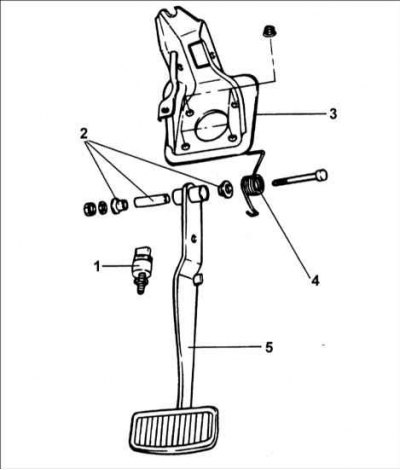
1 – brake light switch; 2 – bushings; 3 – bracket; 4 – spring; 5 – pedal.
Removal
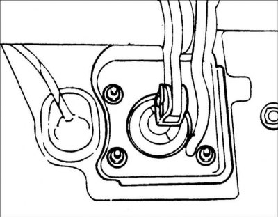
1. Remove the brake light switch.
2. Remove the flange nuts (4EA) and bolt (1EA) securing the brake pedal bracket.
3. Remove the cotter pin and remove the pin with the head and hole for the cotter pin.

4. Remove the brake pedal assembly.
Examination
1. Check the bushing for wear.
2. Check the brake pedal for warping.
3. Check the brake pedal return spring for damage.
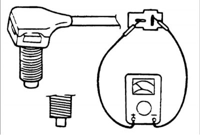
4. Check the brake light switch
- 1) Using an ohmmeter connected to the terminals of the brake light switch, check its conductivity.
- 2) When the plunger is pressed, conductivity should be absent and appear when the plunger is released.
Installation
1. Installation is carried out in the reverse order of removal.
Warning: Make sure to install the cotter pin on the brake pedal linkage pin with a head and a cotter pin hole.
2. Install the brake pedal assembly and secure with the flange nuts and bolt.
Tightening torque: 8–12 Nm
3. Check and, if necessary, adjust the pedal height and free play of the brake pedal.
The material is republished from the web portal hyundaibook.ru
4. Install the brake light switch.