
Contents: Removal ⇓ Installation ⇓ Entering data for individual…⇓ Checking the technical condition ⇓
Removal
Attention.
Since the piezoelectric injector operates on DC power with a maximum voltage of 200 V, there is a risk of electric shock when the control line is shorted, etc. Therefore, when repairing the injector or its wiring, it is necessary to disconnect the negative (-) terminal of the battery and wait for about 30 seconds.
The common rail fuel injection system operates at very high pressure (approximately 1800 bar). Therefore, it is prohibited to carry out work on the injection system while the engine is running or for 30 seconds after the engine has stopped.
It is necessary to keep parts and work area clean.
Pay attention to foreign substances.
The protective cover of the nozzle, tube or hose must be removed immediately before installation.
Do not remove the injector unless necessary.
When installing the injector:
- Clean the contact area of the injector and replace the gasket with a new one.
- To avoid impact damage, insert the injector into the cylinder head vertically.
- Before installing the injector, clean the contact surfaces of the injector gasket and the cylinder head.
When installing the high pressure fuel line:
- Reuse of the high pressure fuel line is not permitted.
- Install the flange nut correctly.
1. Turn the ignition key to the OFF position and disconnect the negative (-) cable from the battery.
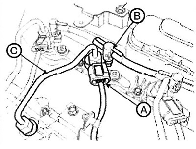
2. Disconnect the injector connector (A) and the injector return line (B).
3. Disconnect the high pressure fuel line (C).
Note: Before connecting or after disconnecting the injector return line, make sure that the plug sleeve is fully lifted out of the plug. Otherwise, fuel will leak out of the injector nipple due to the damaged plug.
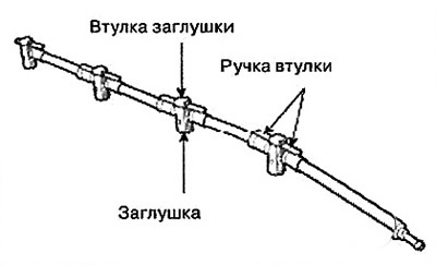
Note: Disconnecting the injector return line.
1. Lift the plug sleeve by pressing on the stop.
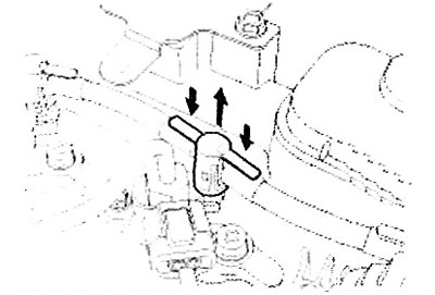
2. Grasp the return line on both sides of the plug and remove the plug by lifting it up from the injector nipple.
4. Loosen the bolt (A) of the injector clamp, then remove the injector (B).
Note: If the injector is jammed in the cylinder head, use the special tool (09351-4A300).

Installation
1. Installation is performed in the reverse order of removal.
Note:
When connecting the high pressure fuel line, tighten the connections to the specified torque using the special tool [09314-27110].
When connecting the high pressure fuel line that connects the fuel rail and the injector, follow the procedure described below.
- Temporarily tighten the nuts onto the fuel rail and injector.
- Connect the injector side and the fuel rail side in series.
Note: Connecting the injector return line: Tightening torque:
- Injector clamp mounting bolt: 29.4 - 33.4 Nm.
- High pressure fuel line fastening nut: 24.5 - 28.4 Nm.
1. When the plug sleeve is fully raised, install the plug onto the injector nipple until it clicks into place.
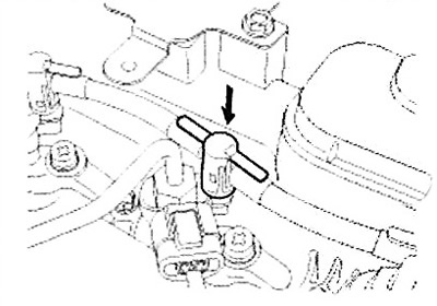
2. Lower the plug sleeve down until it clicks.
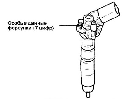
Entering data for individual injectors
Attention: After replacing the injector, it is necessary to enter the injector data (7 digits) for each cylinder into the engine control unit (ECM) using the GDS scanner.
1. Turn off the ignition.
2. Connect the GDS scanner to the data link connector (DLC).
3. Turn on the ignition.
4. Select "Vehicle, Model year, Engine, System".
5. Select "Vehicle S/W Management" (Vehicle Software Management).
6. Select "injector Specific Data".
7. Follow the procedure according to the instructions on the screen.
8. After selecting "OK" in the "Writing success" window, turn off the ignition.
9. After approximately 10 seconds, turn the ignition on and recheck the individual injector data stored in the ECM memory.
Note: If an error occurs, re-enter the individual injector data (7 digits) into the ECM.
Checking the technical condition
Compression check
1. Turn off the ignition.
2. Connect the GDS scanner to the data link connector (DLC).
3. Turn on the ignition.
4. Select "Vehicle, Model year, Engine, System".
5. Select "Vehicle S/W Management" (Vehicle Software Management).
6. Select "Engine Test Function".
7. Select "Compression Test".
8. Perform the test according to the instructions on the screen.
Entering data for individual injectors
Note: If the engine speed for one cylinder is higher than the other cylinders, that cylinder has low compression.
Comparison of idle speeds
1. Turn off the ignition.
2. Connect the GDS scanner to the data link connector (DLC).
3. Turn on the ignition.
4. Select "Vehicle, Model year, Engine, System".
5. Select "Vehicle S/W Management" (Vehicle Software Management).
6. Select "Engine Test Function".
7. Select "Idle Speed Comparision".
8. Perform the test according to the instructions on the screen.
Comparison of fuel injection quantities
1. Turn off the ignition.
2. Connect the GDS scanner to the data link connector (DLC).
3. Turn on the ignition.
4. Select "Vehicle, Model year, Engine, System".
5. Select "Vehicle S/W Management" (Vehicle Software Management).
6. Select "Engine Test Function".
7. Select "Injection Quantity Comparison".
8. Perform the test according to the instructions on the screen.