
Contents: Examination ⇓ Installation ⇓
Tightening torque: Nm
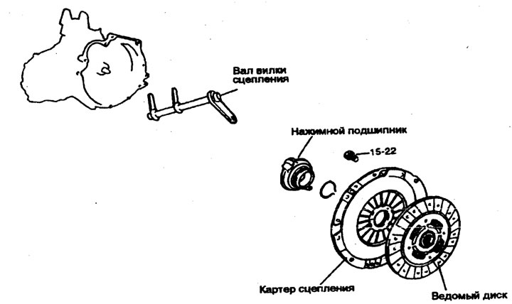
1. To remove the gearbox assembly, first disconnect the air filter, mounting bracket, electrical wiring, etc.
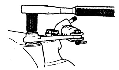
2. Remove the push lever.
- a) Loosen the pressure lever nut.
- b) Remove the pin and spring clip from the slave cylinder.
- c) Remove the push lever.
Note: The transmission assembly cannot be removed without performing these procedures because the clutch housing, thrust bearing, and thrust fork are combined together.
3. Remove the slave cylinder.
4. Remove the gearbox assembly.
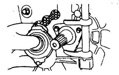
5. Remove the thrust bearing using the special tool shown in the figure.
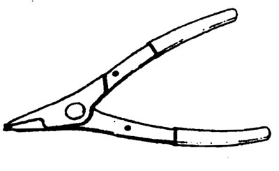
a) Place the tool under the wave washer.
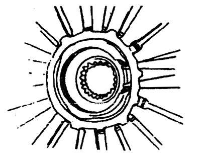
b) Expand the gap around the snap ring by pressing on the bearing as shown in the figure. Then pull the thrust bearing and remove it.
6. Install the special device (09411-11000) into the driven disk to prevent it from falling out.
7. Loosen the clutch housing to flywheel mounting bolts in a star pattern. Loosen each bolt one or two turns each time to avoid warping the clutch housing flange.
Note: Do not clean the clutch disc and thrust bearing with detergents.
8. Remove the clutch fork shaft and sleeve.
Examination
Clutch housing assembly
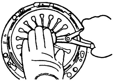
1. Check the wear and equal height of the diaphragm spring ends.
Replace it if the wear is significant or the height difference exceeds the limit.
The limit value is 0.5 mm.
2. Check the pressure plate surface for wear, cracks and discoloration.
3. Check for loose rivets and replace the clutch housing assembly if necessary.
Clutch disc
1. Check the surface for rivets, uneven contact, warping due to binding, adhesion of oil or dirt and replace the driven disc if necessary.
2. Measure the rivet depth and replace the driven disc if it is not within specification.
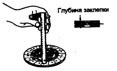
The limit value is 0.3 mm.
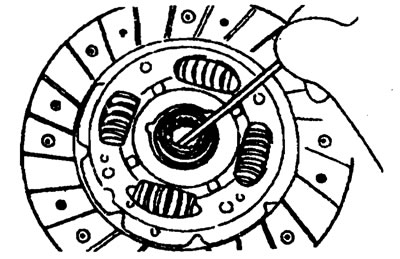
3. Check the torsion spring for play and damage, and if it is faulty, replace the driven disk.
4. Clean the input shaft splines and install the clutch disc. If the disc does not move smoothly or has play, replace the driven disc and/or input shaft.
Clutch thrust bearing
Warning. The thrust bearing contains factory-installed grease. Do not use detergent or other oil to clean it.
1. Check for bearing seizure, damage and noise. Also check the diaphragm spring contact points for wear.
2. Replace the original if the clutch fork contact points have increased wear.
Clutch fork
1. Replace the clutch fork if its contact points with the pressure bearing show excessive wear.
Installation
1. Apply multi-purpose grease to the splines of the driven disc.
Lubricant - MOLIWHITE TA No. 2.
Warning. When installing the clutch, apply grease to each part, but do not use excessive grease as it may get on the clutch driven disc, causing it to slip.
2. Install the clutch driven disc assembly onto the primary shaft using a special tool (09411-11000).

3. Install the clutch housing assembly onto the flywheel and temporarily tighten the clutch housing to flywheel bolts by hand using a star pattern as shown in the figure.
Tightening torque
Clutch housing bolts - 15-22 Nm
4. Align the thrust bearing and clutch fork and install them through the hole in the crankcase.
[The original article is posted on the portal: hyundaibook.ru]
Warning. Apply MOLIWHITE TA #2 multi-purpose grease to the thrust bearing lubrication area and to the contact surface of the clutch fork with the thrust bearing.
5. Connect the push lever to the clutch fork.
6. Install the gearbox.
7. After completing step 6, move the push lever in the direction of the arrow as shown in the figure. A click should be heard indicating that the thrust bearing and clutch housing are properly aligned.
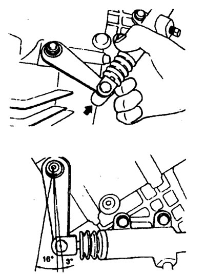
The amount of movement is 3° or less.
If the amount of movement is greater than 3°, this means that the thrust bearing and clutch housing are not aligned correctly. Then move the push lever in the direction of the arrow again.