
Contents: Removal ⇓ Checking the clutch housing ⇓ Checking the slave disk ⇓ Checking the clutch engagement…⇓ Checking the clutch engagement fork ⇓ Installation ⇓
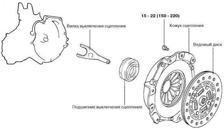
Fig. 3.18. Clutch housing and driven disc
Removal
Drain the fluid from the clutch hydraulic drive and the oil from the gearbox housing.
Remove the gearbox.
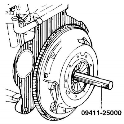
Fig. 3.19. Installing the mandrel into the driven disk hub hole
Insert the 09411-25000 mandrel into the hole in the driven disk hub to prevent it from falling (Fig. 3.19).
Loosen the crosswise tightening of the clutch housing to flywheel mounting bolts.
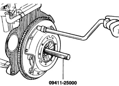
Fig. 3.20. Unscrewing the bolts securing the clutch housing to the flywheel
Loosen the bolts one by one or two turns each time to prevent the casing flange from warping (Fig. 3.20).
Caution! Do not use solvents to clean the driven disc and clutch release bearing.
Checking the clutch housing
Check the ends of the diaphragm spring petals for wear and height differences.
Check the surface of the pressure plate for wear, cracks and discoloration.
Check for loose rivets and replace the clutch cover if necessary.
Checking the slave disk
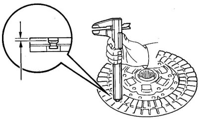
Fig. 3.21. Checking the amount of friction lining protrusion
Check the friction linings for loose rivets, signs of uneven fit, damage from seizure, and oil or grease build-up. If necessary, replace the damaged driven disk (Fig. 3.21).
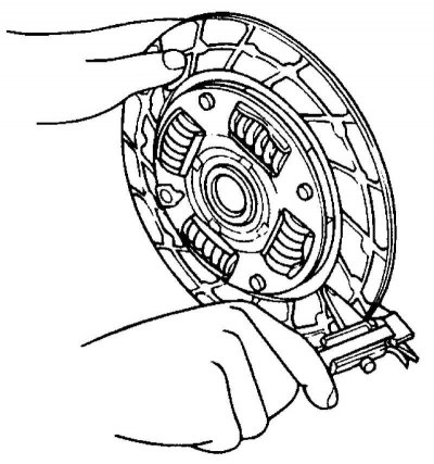
Fig. 3.22. Checking the thickness of the driven disk in a free state
Check the thickness of the driven disk in a free state (Fig. 3.22).
Check the disc springs for play or damage and replace the faulty disc if necessary.
Clean the splines of the gearbox input shaft and install the driven disk.
If the disc moves with difficulty along the shaft splines or there is excessive clearance, replace the driven disc and/or the input shaft of the gearbox.
Checking the clutch engagement bearing
Check the release bearing for binding, damage or excessive noise. Also check the diaphragm spring contact points for wear.
Replace the bearing if the contact points with the clutch release fork are severely worn.
Caution: Since the clutch release bearing contains grease, do not use solvents to clean the bearing.
Checking the clutch engagement fork
Replace the clutch release fork if it is heavily worn where it contacts the clutch release bearing.
Installation
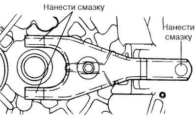
Fig. 3.23. Places to apply universal grease
Apply universal grease to the clutch release fork where it contacts the clutch release bearing and slave cylinder (Fig. 3.23).
Caution! When installing the clutch, do not apply excessive amounts of lubricant to the areas shown in Figure 3.24, as this may cause the clutch to slip and jerk.
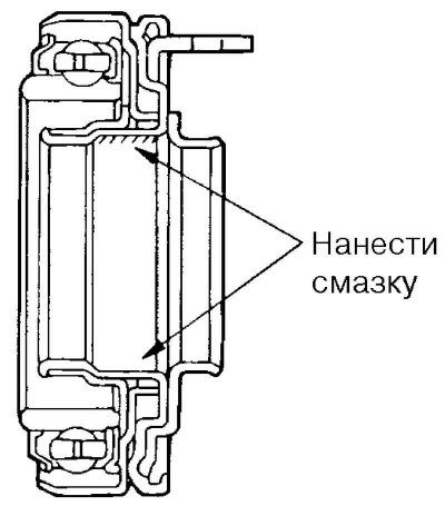
Fig. 3.24. Places of application of universal grease in the bearing groove
Apply CASMOLY L9508 universal grease to the clutch release bearing groove (Fig. 3.24).
Apply CASMOLY L9508 universal grease to the clutch release fork at the point of contact with the clutch release lever axle.
Clean the flywheel and pressure plate surfaces thoroughly with sandpaper or fine emery cloth and make sure there are no traces of oil or grease on them.
Apply a small amount of CASMOLY L9508 universal grease to the splines of the driven disk hub and the gearbox input shaft.
Caution! Apply only the required amount of grease. Excessive grease may cause slippage and clutch jerking.
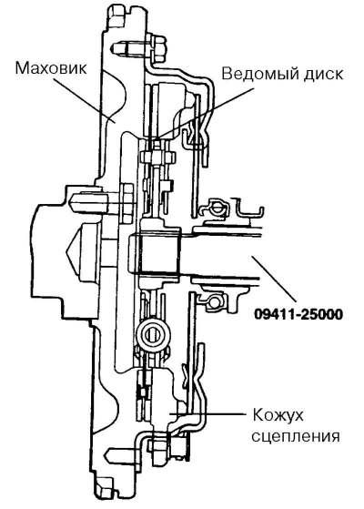
Fig. 3.25. Installing the driven disk on the flywheel
Using the 09411-25000 tool, install the driven disk on the flywheel with the side with the factory marking facing the pressure plate (Fig. 3.25).
Install the clutch housing onto the flywheel and tighten the six mounting bolts.
Tighten the bolts crosswise to 15–22 N·m. Tighten the bolts alternately by one or two turns each time to prevent warping of the clutch housing flange.
Remove the driven disk centering mandrel.
Install the gearbox.
Adjust the clutch pedal free play.