


Contents: Removal ⇓ Checking the technical condition ⇓ Installation ⇓ Post-installation check ⇓ Assembly ⇓
Removal
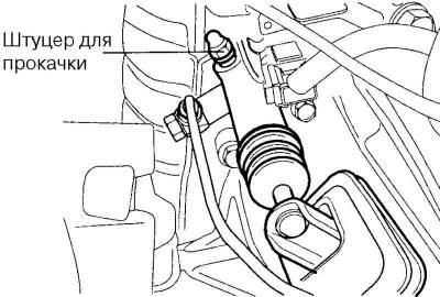
Fig. 3.6. Bleed nipple
Drain the working fluid through the bleed nipple (Fig. 3.6).
Loosen the master cylinder mounting nut.
Disconnect the pipes.
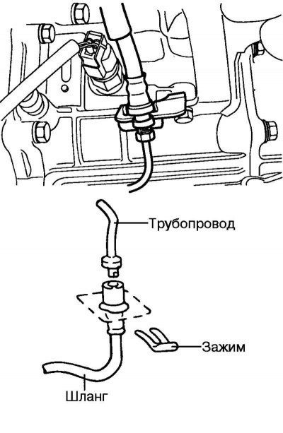
Fig. 3.7. Pipeline fastening clamp to the gearbox
Remove the clamp securing the pipeline to the gearbox (Fig. 3.7).
Checking the technical condition
Check the hose and line for rust, pitting and scoring.
Installation
Connect the pipe to the working cylinder.
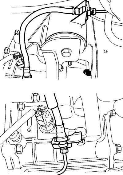
Fig. 3.8. Connecting hoses
Attach the hose and secure it with a clamp (Fig. 3.8).
Install the master cylinder.
Attach the push rod to the clutch pedal.
Bleed the clutch hydraulic system.
Remove the piston retaining ring.
Remove the push rod assembly with the piston.
Note: When doing this, be careful not to damage the cylinder body and piston.
Post-installation check
Check the cylinder bore for rust, pitting and scoring.
Check the cylinder seal for wear or distortion.
Check the piston for rust, pits or scoring.
Check the cleanliness of the pipeline.
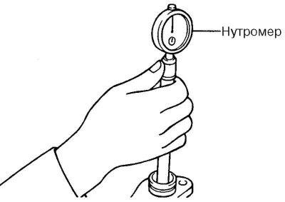
Fig. 3.9. Checking the cylinder diameter using a bore gauge
Check the inner diameter of the cylinder using a bore gauge and the outer diameter of the piston using a micrometer (Fig. 3.9).
If the clearance between the piston and cylinder exceeds the maximum permissible value, replace the master cylinder or piston.
Maximum permissible clearance between the piston and the cylinder: 0.15 mm.
Assembly
Apply DOT3 or DOT4 brake fluid to the cylinder bore and outer surface of the piston.
Insert the piston into the cylinder.
Install the piston retaining ring.
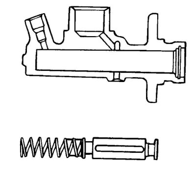
Fig. 3.10. Installing the pusher
Install the pusher (see master cylinder parts) (Fig. 3.10).
Attach the hose to the cylinder body.