Contents: Checking the fluid level in the…⇓ Checking the operation of the…⇓ Adjusting the gear shifter ⇓ Adjusting the downshift servo ⇓ Line pressure regulation ⇓ Replacing axle shaft seals ⇓
Checking the fluid level in the gearbox
See the relevant section at the beginning of this chapter.
Checking the operation of the selector lever
1. Move the lever to each position and make sure it moves smoothly. Check that it is fixed correctly.
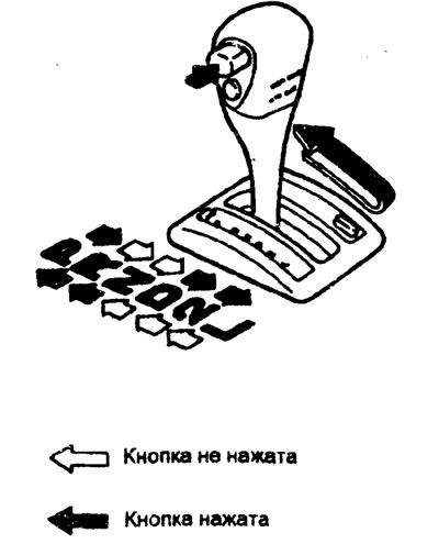
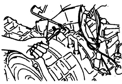
2. Make sure that the lever can be moved to any position (using the button as shown in the picture).
3. Start the engine and check that the vehicle moves forward when the shift lever is moved from the "N" position to the "D" position and moves backward when the shift lever is moved to the "R" position.
4. If the lever is faulty, adjust the control cable and lever coupling. Check the wear of the sliding parts of the selector lever assembly.
Adjusting the gear shifter
1. Set the gearshift lever to the "N" position (neutral).
2. Loosen the manual control lever flange nut to release the lever cable.
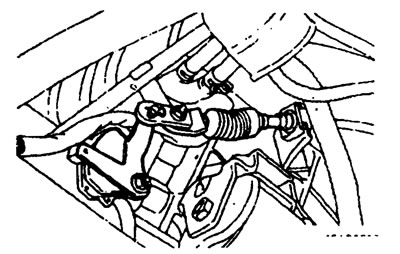
3. Set the manual control lever to the "N" position (neutral).
4. Rotate the gearshift housing until the end of the 12mm wide manual control lever aligns with the flange of the gearshift housing (12mm wide section).
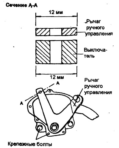
5. Tighten the bolts to the required torque of 10-12 Nm.
6. Make sure the shift lever is in the "N" position (neutral)
7. Adjust the flange nut so that there is no slack in the control cable and make sure that the shift lever moves smoothly.
8. While the vehicle is moving, make sure that all gears in the gearbox are engaged when the shift lever is moved to each position.
Adjusting the downshift servo
1. Completely remove dirt and other debris around the servo switch.
2. Loosen the lock nut.
3. Loosen the adjusting screw two turns and then finally tighten to a torque of 5 Nm.
4. After tightening the adjusting screw to a torque of 5 Nm, loosen the adjusting screw by 3-3½ turns.
5. Tighten the lock nut to the specified torque.
Lock nut - 15-22 Nm.
Note: Apply proper amount of grease (DC780) to the adjusting screw before assembly.
Line pressure regulation
1. Drain the fluid from the gearbox.
2. Remove the oil pan.
3. Remove the oil filter.
4. Remove the oil temperature sensor.
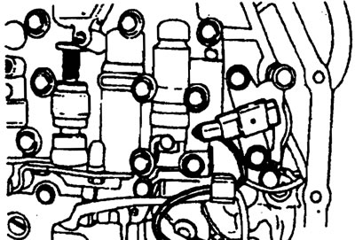
5. Press the solenoid valve wiring seal tab and push it out.
6. Remove the manual control valve body assembly. Make sure that the valve does not fall out.
7. Turn the valve adjusting screw and adjust the line pressure (servo brake pressure) to the standard value. When you turn the adjusting screw clockwise, the pressure will begin to decrease; when you turn it in the opposite direction, it will increase.
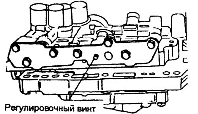
Nominal value - 860-900 kPa
For each turn of the adjusting screw, the oil pressure will change by 38 kPa.
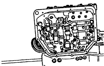
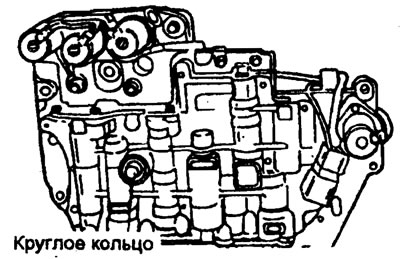
8. Make sure that the sealing ring is installed on the valve body surface as shown in the figure.
9. Replace the solenoid valve connector O-ring with a new one.
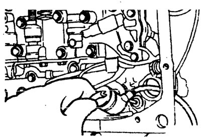
10. Install the valve body onto the crankcase and insert the solenoid valve connector into the crankcase. Make sure that the marked part of the connector surface is positioned as shown in the figure.
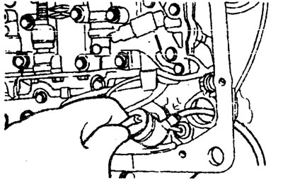
Also make sure that the electrical wiring is not pinched.
11. Tighten the ten (10) valve body mounting bolts to 10-12 Nm.
- A - 25 mm long
- B - 35 mm long
- C - 40 mm long
12. Install the oil filter.
13. Install the new oil pan gasket and oil pan.
14. Add the required amount of automatic transmission fluid.
15. Check the oil pressure. If necessary, readjust.
Replacing axle shaft seals
1. Disconnect the axle shaft from the gearbox (See chapter "Front suspension").
2. Using a flat-head screwdriver, remove the oil seal.
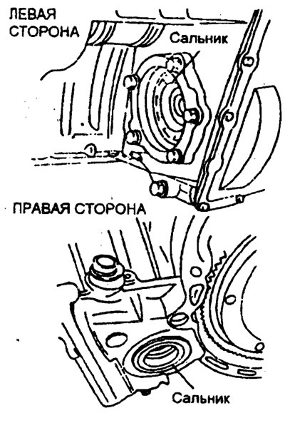
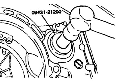
3. Using a special tool (09431-21200), install the axle shaft seal into the gearbox housing.
4. Apply a layer of transmission fluid to the working lip of the oil seal.