Warning:
- Since the gearbox consists of high-precision manufactured parts, these parts must be handled with extreme care during disassembly and assembly to avoid damage.
- A rubber mat should be placed on the workbench. During disassembly, do not use gloves made of fabric or rags. If necessary, use nylon products or paper napkins. Metal parts can be cleaned with regular detergents followed by thorough air drying.
- The clutch disc, pressure plate and rubber parts must be cleaned using automatic transmission fluid.
1. Remove sand, dirt, etc. from the entire surface of the gearbox.
2. Place the gearbox on the workbench with the crankcase facing down.
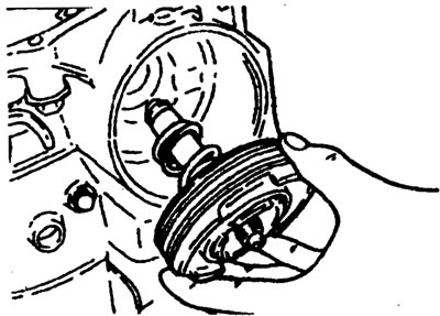
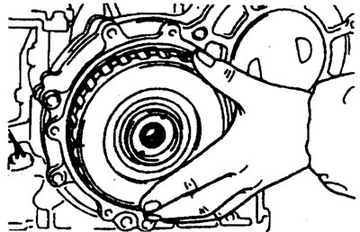
3. Remove the torque converter.
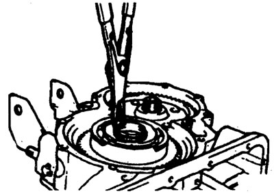
4. Measuring the input shaft end play before disassembly will usually determine if the thrust washer needs to be replaced (except when major parts are replaced).
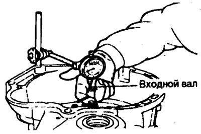
Standard value is 0.3-1.0 mm
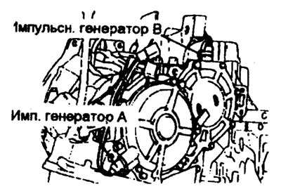
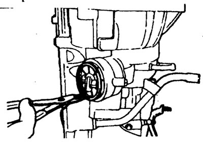
5. Remove pulse generators "A" and "B".
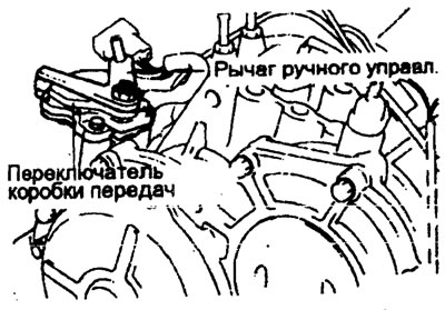
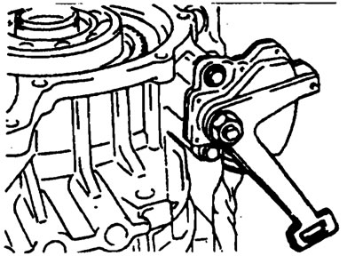
6. Remove the manual control lever, then remove the transmission range switch.
7. Remove the snap ring and servo switch.
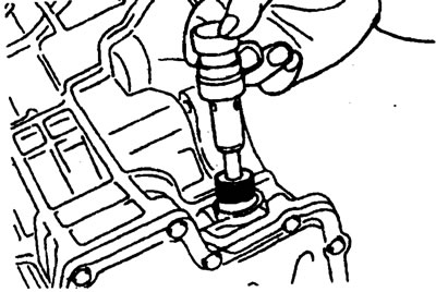
8. Remove 6 bolts using a special tool (09452-21100) and remove the oil pump assembly.
9. Remove the fiber thrust washer.
10. Remove the drive shaft and remove the front and rear couplings.
11. Remove the thrust bearing.
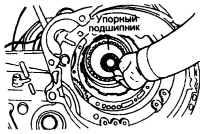
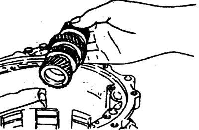
12. Remove the clutch hub.
13. Remove the thrust bearing ring and bearing.
14. Remove the downshift servo drum.
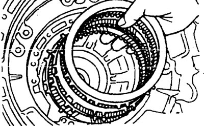
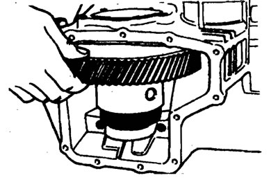
15. Remove the servo belt.
16. Remove the spring retaining ring.
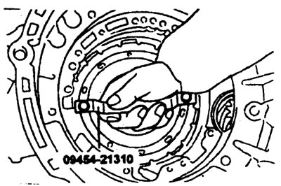
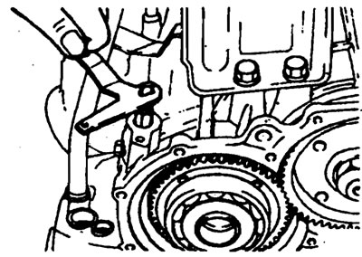
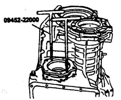
17. Attach special tools (09453-21310) to the central support. Holding the handle, pull the center support straight up.
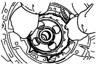
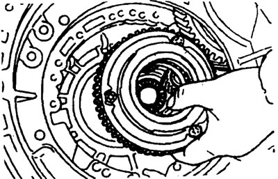
18. Remove the forward and reverse gear wheels.
19. Remove the planetary gear support and thrust bearing.
20. Remove the wave spring, return spring, backing plate, brake disc and brake plate.
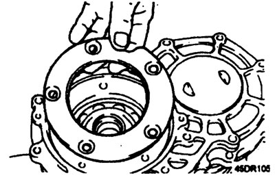
21. Remove the bolts securing the end sleeve cover, the cover mount and the end sleeve cover.
22. Remove the end sleeve.
23. Remove the thrust plate.
24. Remove the end sleeve hub and thrust bearing.
25. Remove the end coupling shaft.
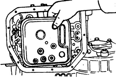
26. Remove the oil pan and gasket.
27. Remove the oil filter from the valve body.
28. Loosen the oil temperature sensor mounting bolt; after removing it from the bracket side, pull it out from the connector side.
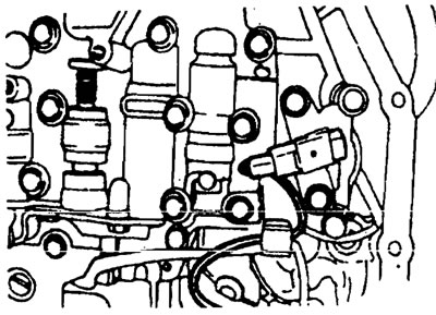
29. Compress the tabs of the solenoid valve wiring sleeve and insert it.
30. Unscrew the 10 valve body bolts and remove the body.
31. Using an impact tool, loosen the bolt. If you do not have an impact tool, use a chisel or similar tool.
32. Remove the bearing separator.
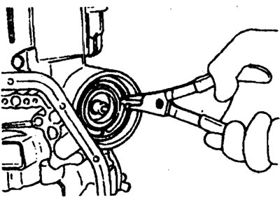
33. Remove the snap ring from the bearing.
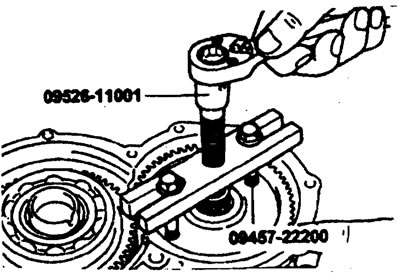
34. Loosen the bolts securing the back cover and remove the back cover.
35. Remove the cotter pin from the transmission shaft lock nut.
36. Set the lever to position "P".
37. Remove the lock nut.
38. Using the special tool, remove the driven gear of the transmission shaft.
39. Remove the outer race of the tapered roller bearing.
40. Remove the spring retaining ring.
41. Remove the transmission shaft and tapered roller bearing.
42. Move the manual control lever from position "P" to position "N".
43. Remove the spring retaining ring from the outer flange.
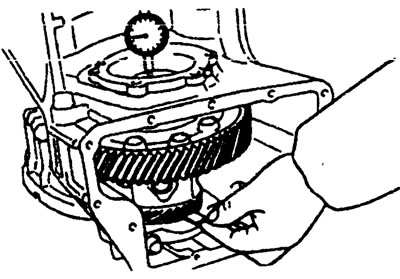
44. Remove the locking plate.
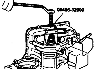
45. Using a special tool or a press, remove the outer flange and drive gear.
46. Remove the speedometer bushing.
47. Remove the differential cover and gasket.
48. Before removing the differential gear, measure the differential gear axial play using a dial gauge.
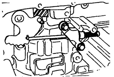
Standard value is 0-0.15 mm
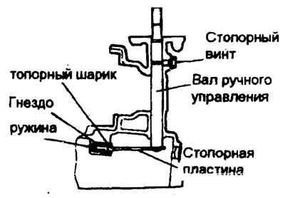
49. Remove the 5 bolts securing the differential bearing separator.
50. Using the special tool, remove the differential bearing separator.
51. Loosen the mounting bolts and remove the bearing cover.
52. Remove the differential.
53. Loosen the two bolts and remove the parking spacer rod.
54. Loosen the lock screw and remove the manual control shaft assembly. Remove the steel ball, its seat and spring at the same time.
55. Remove the downshift servo spring retaining ring.
56. Remove the servo piston assembly.