
Contents: Removal ⇓ Installation ⇓
List of elements for the drawings
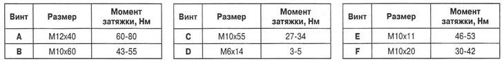
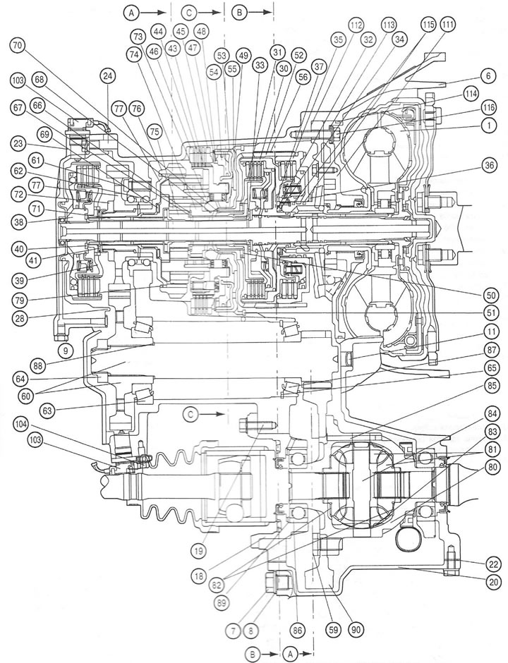
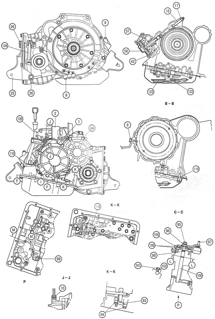
1. Torque converter; 2. Gearbox support bracket; 3. Washer; 4. Front powertrain support bracket; 5. Washer; 6. Gearbox housing; 7. Drain plug; 8. Gasket; 9. Oil channel plug; 10. ATF radiator hose nipple; 11. Lid; 12. Oil pan; 13. Magnet; 14. Gasket; 15. Screw; 16. Adjusting screw; 17. Nut; 18. Differential bearing holder; 19. Screw; 20. Main gear housing cover; 21. Washer; 22. Gasket; 23. Rear cover of the gearbox housing; 24. Screw; 25. Bracket of rear support of power unit; 26. Screw; 27. Screw; 28. Sealing ring; 29. Sapun; 30. Rear friction clutch; 31. Rear clutch hub; 32. Thrust bearing; 33. Thrust bearing; 34. Bearing race; 35. Front friction clutch; 36. Thrust washer; 37. Thrust washer; 38. End coupling; 39. End coupling hub; 40. Thrust washer; 41. Thrust bearing; 42. Retaining ring; 43. Brake disc; 44. Friction disc; 45. Pressure plate; 46. Thrust disc; 47. Return spring; 48. Spring; 49. Thrust bearing; 50. Bearing race; 51. Retaining ring; 52. Low gear engagement brake drum; 53. Sealing ring; 54. Downshift and reverse brake piston; 55. Central support; 56. Band brake of the reduction gear; 57. Downshift brake piston; 58. Low gear switch; 59. Screw; 60. Driven gear of intermediate transmission; 61. Screw; 62. Ball bearing; 63. Roller bearing; 64. Lock nut; 65. Retaining ring; 66. Thrust bearing; 67. Bearing race; 68. Seal; 69. Thrust bearing; 70. Retaining ring; 71. End coupling shaft; 72. Lock nut; 73. Planetary gear carrier; 74. Reverse gear sun gear; 75. Forward gear sun gear; 76. Ring gear; 77. Intermediate drive pinion; 78. Flange; 79. Retaining ring; 80. Satellite box; 81. Differential gears; 82. Thrust washer; 83. Gear washer; 84. Axle of satellites; 85. Locking pin; 86. Ball bearing; 87. Side bearing; 88. Distance washer; 89. Distance washer; 90. Driven gear of the main transmission; 91. Speedometer drive gear; 92. Locking plate; 93. Rod support; 94. Screw; 95. Nut; 96. Spring washer; 97. Manual control lever; 98. Sealing ring; 99. Screw; 100. Manual control shaft; 101. Screw; 102. Sealing ring; 103. Shaft speed sensor; 104. Screw; 105. Automatic transmission selector position sensor; 106. Screw; 107. Selector cable bracket; 108. Screw; 109. Clamp; 110. Retaining ring; 111. Oil pump; 112. Gasket; 113. Sealing ring; 114. Sealing ring; 115. Sealing ring; 116. Screw; 117. Valve assembly; 118. Transmission fluid temperature sensor; 119. Screw; 120. Screw; 121. Screw; 122. Oil filter; 123. Screw; 124. Speedometer drive gear bushing; 125. Screw; 126. Filler neck; 127. Screw; 128. Oil dipstick.
1. Torque converter; 2. Gearbox support bracket; 3. Washer; 4. Front powertrain support bracket; 5. Washer; 6. Gearbox housing; 7. Drain plug; 8. Gasket; 9. Oil channel plug; 10. ATF radiator hose nipple; 11. Lid; 12. Oil pan; 13. Magnet; 14. Gasket; 15. Screw; 16. Adjusting screw; 17. Nut; 18. Differential bearing holder; 19. Screw; 20. Main gear housing cover; 21. Washer; 22. Gasket; 23. Rear cover of the gearbox housing; 24. Screw; 25. Bracket of rear support of power unit; 26. Screw; 27. Screw; 28. Sealing ring; 29. Sapun; 30. Rear friction clutch; 31. Rear clutch hub; 32. Thrust bearing; 33. Thrust bearing; 34. Bearing race; 35. Front friction clutch; 36. Thrust washer; 37. Thrust washer; 38. End coupling; 39. End coupling hub; 40. Thrust washer; 41. Thrust bearing; 42. Retaining ring; 43. Brake disc; 44. Friction disc; 45. Pressure plate; 46. Thrust disc; 47. Return spring; 48. Spring; 49. Thrust bearing; 50. Bearing race; 51. Retaining ring; 52. Low gear engagement brake drum; 53. Sealing ring; 54. Downshift and reverse brake piston; 55. Central support; 56. Band brake of the reduction gear; 57. Downshift brake piston; 58. Low gear switch; 59. Screw; 60. Driven gear of intermediate transmission; 61. Screw; 62. Ball bearing; 63. Roller bearing; 64. Lock nut; 65. Retaining ring; 66. Thrust bearing; 67. Bearing race; 68. Seal; 69. Thrust bearing; 70. Retaining ring; 71. End coupling shaft; 72. Lock nut; 73. Planetary gear carrier; 74. Reverse gear sun gear; 75. Forward gear sun gear; 76. Ring gear; 77. Intermediate drive pinion; 78. Flange; 79. Retaining ring; 80. Satellite box; 81. Differential gears; 82. Thrust washer; 83. Gear washer; 84. Axle of satellites; 85. Locking pin; 86. Ball bearing; 87. Side bearing; 88. Distance washer; 89. Distance washer; 90. Driven gear of the main transmission; 91. Speedometer drive gear; 92. Locking plate; 93. Rod support; 94. Screw; 95. Nut; 96. Spring washer; 97. Manual control lever; 98. Sealing ring; 99. Screw; 100. Manual control shaft; 101. Screw; 102. Sealing ring; 103. Shaft speed sensor; 104. Screw; 105. Automatic transmission selector position sensor; 106. Screw; 107. Selector cable bracket; 108. Screw; 109. Clamp; 110. Retaining ring; 111. Oil pump; 112. Gasket; 113. Sealing ring; 114. Sealing ring; 115. Sealing ring; 116. Screw; 117. Valve assembly; 118. Transmission fluid temperature sensor; 119. Screw; 120. Screw; 121. Screw; 122. Oil filter; 123. Screw; 124. Speedometer drive gear bushing; 125. Screw; 126. Filler neck; 127. Screw; 128. Oil dipstick.
Removal
Note: Label all hoses and connectors before disconnecting.
1. Disconnect the wires first from the negative terminal of the battery, and then from the positive terminal.
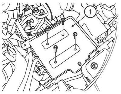
2. Remove the battery and shelf (1).
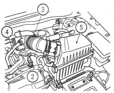
3. Disconnect the air flow sensor connector (2). Disconnect the air duct (3) and ventilation hose (4). Remove the air filter cover (5).
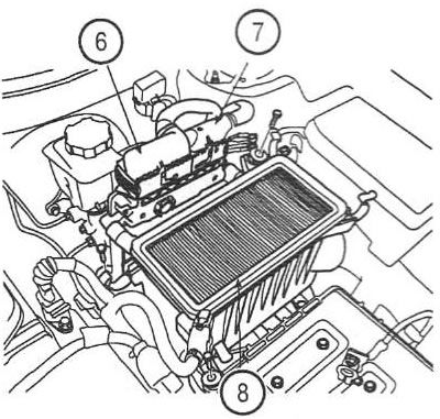
4. Disconnect the connectors (6 and 7) of the engine control unit. Remove the filter element and remove the air filter housing (8).
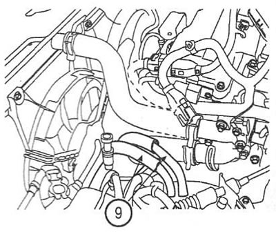
5. Disconnect the transmission fluid radiator pipes (9).
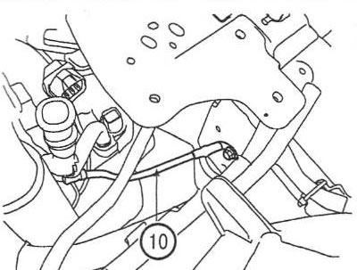
6. Disconnect the ground wire (10) from the gearbox.
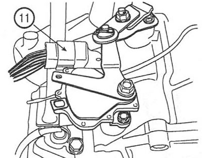
7. Disconnect the selector position sensor connector (11).
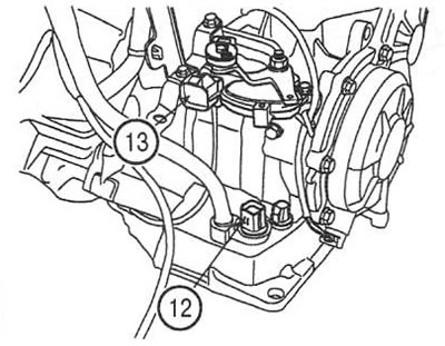
8. Disconnect the connectors of the solenoid valve assembly (12) and the transmission fluid temperature sensor (13).
9. Disconnect the connectors of the speedometer sensor (14), the downshift switch (15), the input (16) and output (17) shaft speed sensors.
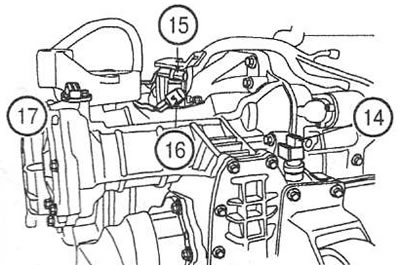
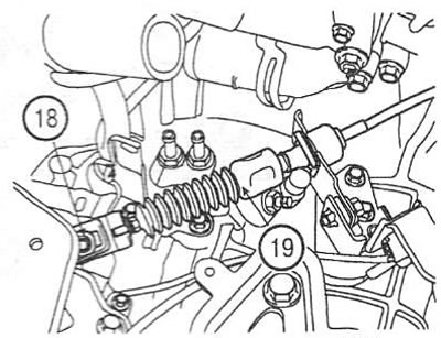
10. Unscrew the nut (18) and disconnect the selector lever cable (19).
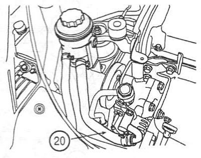
11. Disconnect the power steering feed pipe (20) and drain the fluid.
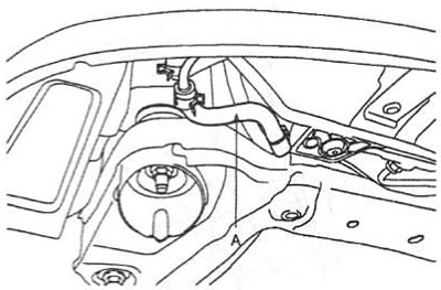
12. Disconnect the power steering return pipe (21).
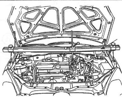
13. Install the crossbar with stands and hook the engine lifting eyes with hooks.
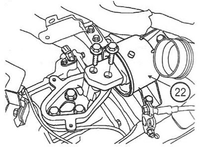
14. Loosen the gearbox support bracket screws (22). Tightening torque: 70-95 Nm.
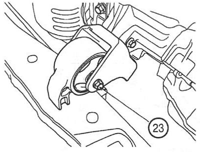
15. Unscrew the bolt (23) of the front support of the power unit. Tightening torque: 50-65 Nm.
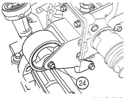
16. Unscrew the bolt (24) of the rear support of the power unit. Tightening torque: 5065 Nm.
17. Remove the front and side engine mudguards.
18. Remove the front wheels.
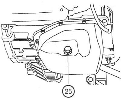
19. Unscrew the drain plug of the automatic transmission pan (25) and drain the transmission fluid. Tightening torque: 35-45 Nm.
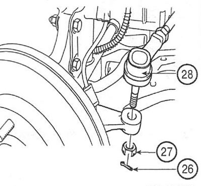
20. Remove the cotter pin (26), unscrew the nut (27) and disconnect the steering rod end (28) from the steering knuckle on both sides.
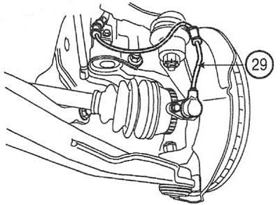
21. Remove the wheel speed sensors (29).
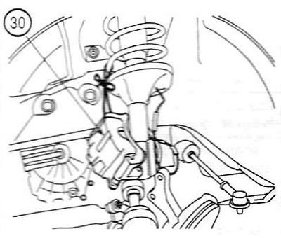
22. Remove the brake calipers (30) and secure them to the shock absorber struts
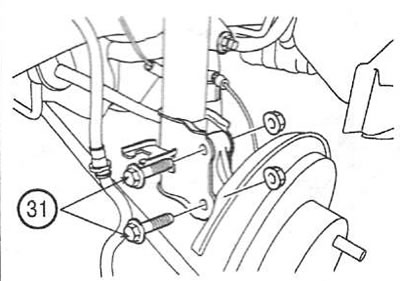
23. Open the bolts 31) of the steering knuckle on both sides.
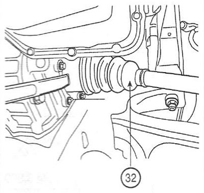
24. Separate the drive shafts (32) from the gearbox.
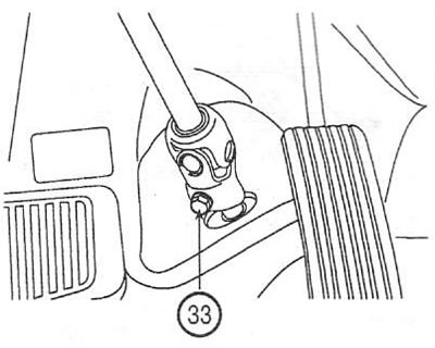
25. Unscrew the bolt (33) of the intermediate shaft joint.
26. Support the gearbox with a lift.
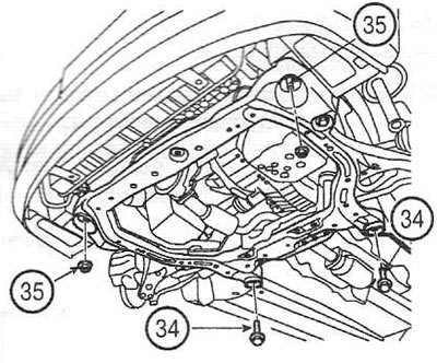
27. Unscrew the screws (34) and nuts (35) of the engine subframe. Tightening torque: 40-50 Nm (screws); 160-180 Nm (nuts).
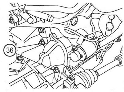
28. Loosen the starter screws (36). Tightening torque: 27-34 Nm.
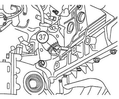
29. While turning the crankshaft, unscrew the torque converter screws (37). Tightening torque: 48-53 Nm.
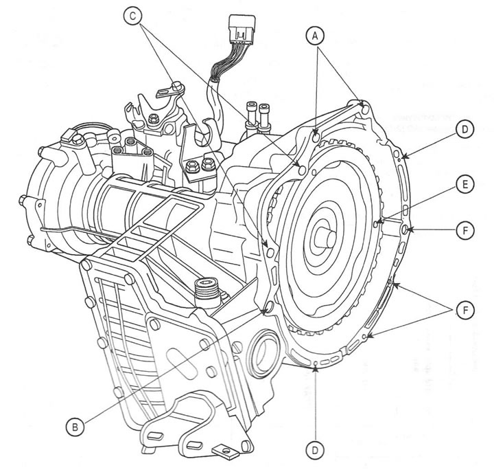
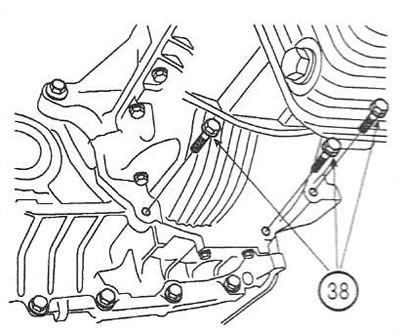
30. Loosen the gearbox-to-engine mounting screws (38). Tightening torque: 60-80 Nm (M12 screws): 43-55 Nm (M10 screws).
31. Remove the gearbox.
Installation
32. Installation is carried out in the reverse order of removal.
33. After installing the gearbox, perform the following procedures:
- fill the gearbox with clean transmission fluid;
- fill the power steering system with working fluid;
- check for leaks from hoses and pipes;
- adjust the cable of the lever and selector position sensor.