Note: Tightening torque: 78.5-93.2 Nm.
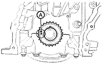
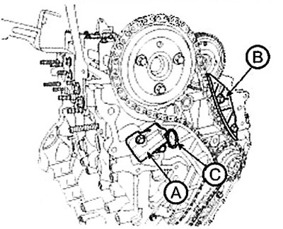
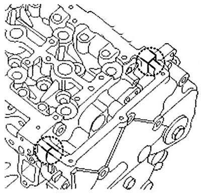
Note: It is necessary to align the timing mark (A) of the crankshaft sprocket with the cylinder block. This will set the piston of cylinder No.1 to the top dead center position of the compression stroke.
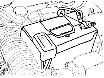
Note: Tighten the high pressure fuel pump sprocket nut, securing the ring gear with the special stopper (09231-2B100) (A).
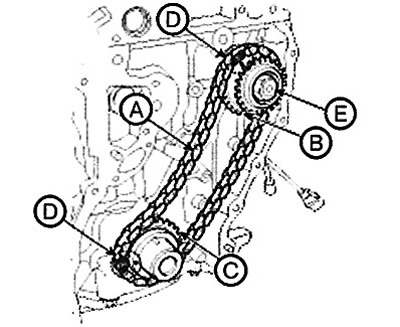
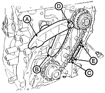
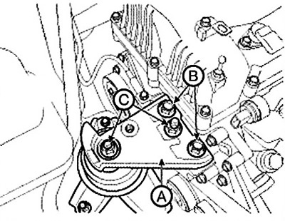
2. Install the lever (A) of the "B" chain of the gas distribution mechanism drive, the lever (B) of the "A" chain of the gas distribution mechanism drive, and the guide (C) of the "A" chain of the gas distribution mechanism drive.
Note: Tightening torque:
- Bolt (D): 29.4-31.4 Nm.
- Bolts (E): 9.8-11.8 Nm.
Do not reuse the tensioner arm and guide mounting bolt. If necessary, the bolt can be reused after removing the hard sealant and applying sealant (LOCTITE 262, THREEBOND 1324N or equivalent) to the threaded portion of the bolt.
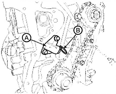
3. Install the automatic tensioner (A) of the timing chain "A" and remove the installation pin (B).
Note: Tightening torque: 9.8-11.8 Nm.
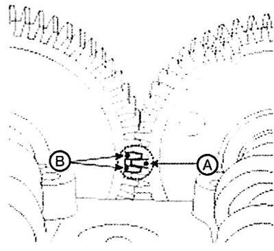
4. Make sure that the timing mark (A) of the exhaust camshaft gear and the timing mark (B) of the intake camshaft gear are aligned as shown in the illustration.
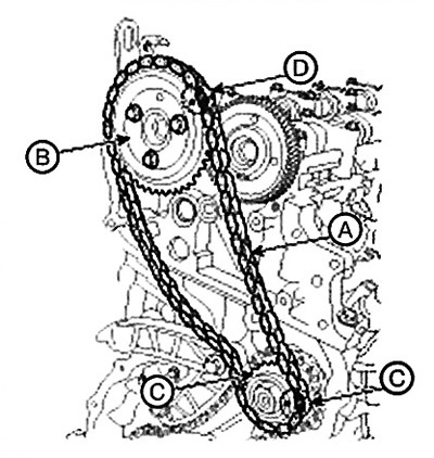
5. After installing the timing chain (A) "B" and aligning the timing marks (D) of the high-pressure pump sprocket (C) and the camshaft sprocket (B), install the camshaft sprocket onto the exhaust camshaft gear.
Note: Tightening torque: 14.7-19.6 Nm.
6. Install the timing chain "B" automatic tensioner (A) and guide (B), then remove the mounting pin (B).
Note: Tightening torque: 9.8-11.8 Nm.
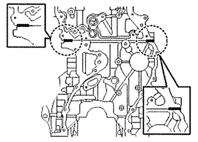
7. Apply sealant to the mating surfaces of the timing chain cover.
Note:
- Standard sealant: LOCTITE 5900H or equivalent.
- Before applying sealant, ensure that the mating surfaces are clean and dry.
- After applying the sealant, wait five minutes and install the timing chain cover.
- Apply the sealant in a 3mm wide bead without stopping.
- Remove the hard sealant at the front between the block and head.
- Apply a 4mm thick bead of sealant in an L shape to the T-joint.
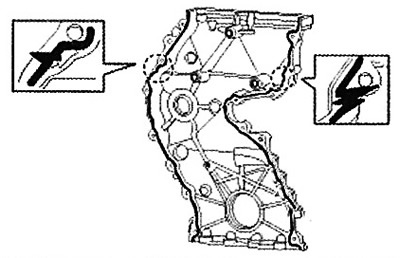
Apply sealant to the front area between the block and head.
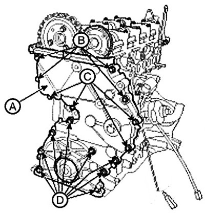
8. Install the timing chain cover (A).
Note:
Tightening torque:
- Bolts (B): 19.6 - 24.5 Nm.
- Bolts (C, D): 7.8 - 11.8 Nm.
Note:
- Check the surface roughness between the timing chain and the cylinder head.
- Unevenness: 0.20mm or less.
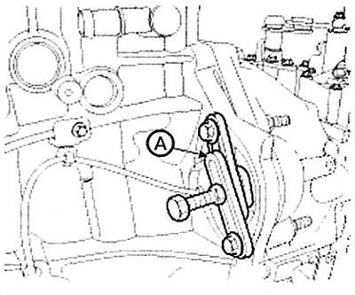
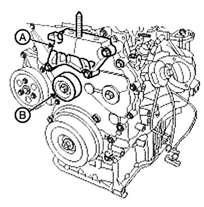
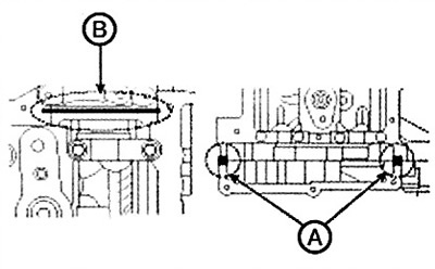
9. Install the engine support bracket (A) and the drive belt idler roller (B).
Note: Tightening torque: 42.2 - 53.9 Nm.
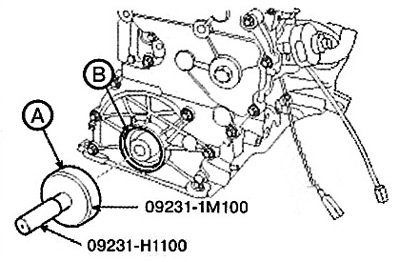
10. Install the front oil seal using the special tool (09231-1M100, 09231-H1100) (A).
11. Install the crankshaft vibration damper pulley (A).
Note: Tightening torque: 196.1 Nm + 60° further tightening.
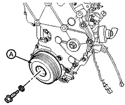
Tighten the crankshaft vibration damper bolt, securing the ring gear with a special stopper (09231-2B100) (A).
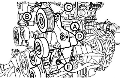
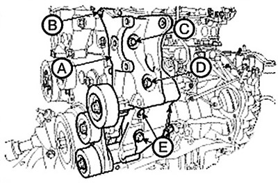
12. Install the accessory drive system bracket (A) assembly.
Note: Tightening torque:
- Bolts (B, C, D): 19.6 - 26.5 Nm.
- Bolts (E): 42.2.0-53.9 Nm.
Type MDPS
HPS type
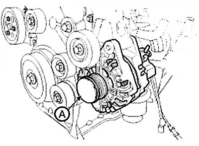
13. Install the generator (A).
Note: Tightening torque: 49.0 - 63.7 Nm.
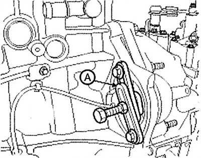
14. Install the engine mount bracket (A).
Note: Tightening torque: Bolts (B), nuts (C): 63.7-83.4 Nm.
15. Remove the jack from under the cylinder block.
16. Apply sealant evenly to the mating surfaces of the upper oil pan.
Note:
- Standard sealant: LOCTITE 5900H or equivalent.
- Before applying sealant, ensure that the mating surfaces are clean and dry.
- Apply a 4mm thick bead of sealant (5mm or more for T-joints); 3.5mm for the rear oil seal) without stopping.
- After applying the sealant, wait five minutes and install the oil pan.
- After installing the oil pan, wait at least 30 minutes before adding oil to the engine.
- After installation, remove excess sealant from the rear oil seal area.
- Before installing the upper oil pan, remove any excess sealant squeezed out from the contact surface between the cylinder block and the timing chain cover.
Caution: Avoid applying too much sealant or applying sealant in the wrong direction. If sealant gets into the installation holes of the rear oil seal housing assembly, it may cause contamination or cracking.
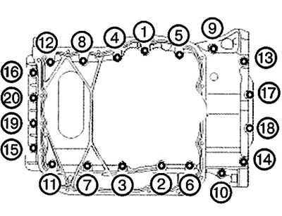
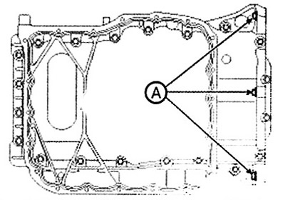
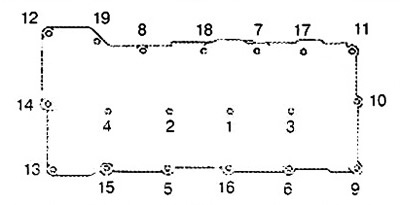
17. Install the upper oil pan (A).
(1) Tighten the bolts in the order shown.
Note: Tightening torque: 9.8-11.8 Nm.
(2) Tighten the transmission housing bolts (A).
Note: Tightening torque: 39.2-46.1 Nm
18. Apply sealant evenly to the mating surfaces of the lower oil pan.
Note:
- Standard sealant: LOCTITE 5900H or equivalent.
- Before applying sealant, ensure that the mating surfaces are clean and dry.
- Apply sealant in a continuous 4mm thick bead.
- After applying the sealant, wait five minutes and install the oil pan.
- After installing the oil pan, wait at least 30 minutes before adding oil to the engine.
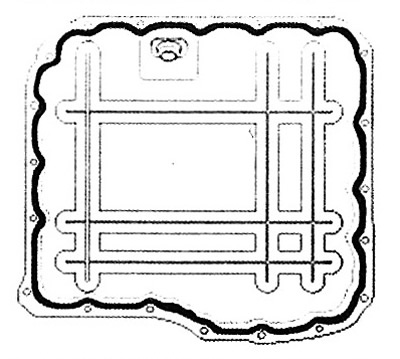
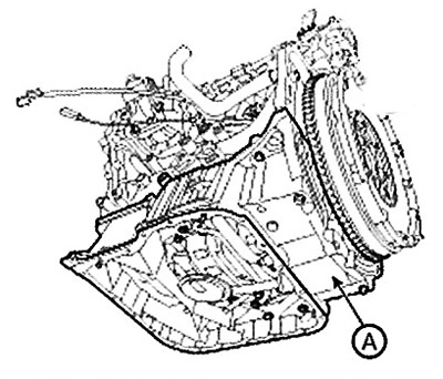
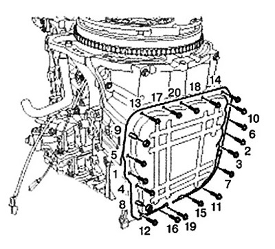
19. Install the lower oil pan. Tighten the bolts in the order shown.
Note: Tightening torque: 9.8 - 11.8 Nm.
20. Install the air compressor (A).
21. Install the oil filter and oil cooler assembly (A).
Note: Tightening torque: 19.6-26.5 Nm.
Caution: When installing the oil filter and oil cooler assembly, check for O-rings on the mating surface with the cylinder block. Tighten the 4 upper bolts first, then tighten the remaining lower bolt.
22. Install the cylinder head cover (A) using new gaskets (B, C).
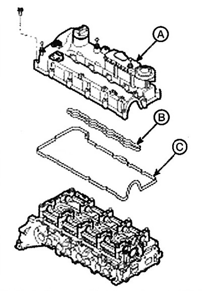
Tighten the cylinder head cover bolts as follows.
Tightening torque:
- 1 step: 3.9-5.9 Nm.
- 2 step: 8.8-10.8 Nm.
Note:
- Standard sealant: LOCTITE 5900H or equivalent.
- Before applying sealant, ensure that the mating surfaces are clean and dry.
- After applying the sealant, wait five minutes and install the cylinder head cover.
- After installation, wait at least 30 minutes before adding oil to the engine.
- Before installing the cylinder head, remove any harmful material (engine oil, cutting fluid) from the top of the cylinder head and timing chain cover.
- Remove the hard sealant at the top between the cylinder head and the timing chain cover.
- Before installing the cylinder head cover, make sure that the protrusion of the head cover gasket fits exactly into the hole in the head cover.
- Before installing the cylinder head cover, apply sealant to the T-joints at the top between the cylinder head and the timing chain and at the rear of the camshaft carrier.
23. Install the power steering pump (B) and connect the power steering oil hoses (A). (HPS only).
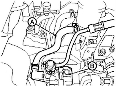
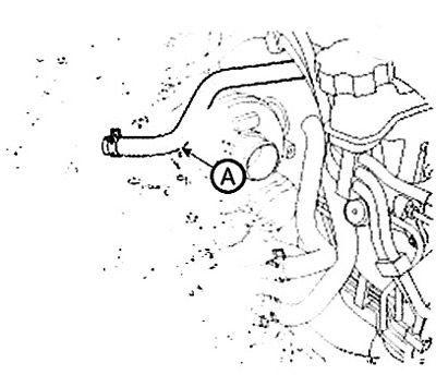
24. Connect the vacuum hose (A).
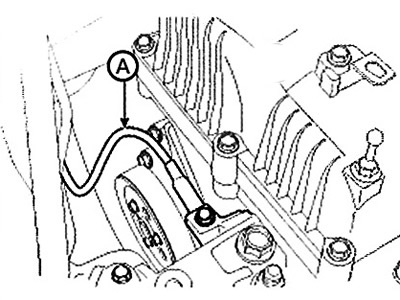
25. Connect the breather hose (A).
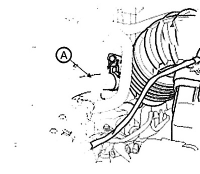
26. Connect the engine ground wire (A).
27. Install the injectors and connect the high pressure pipes (B), fuel return hose (C) and vacuum hose (D) of the exhaust gas recirculation (EGR) system, then connect the connectors (A) of the injectors.
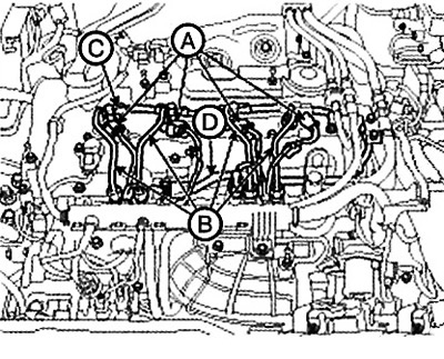
Standard power
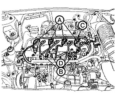
Reduced power
Note: Reuse of high pressure fuel line and injector gaskets is not permitted.
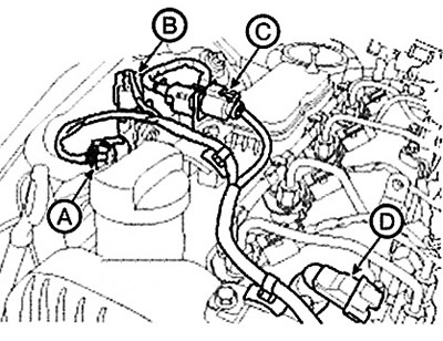
28. Connect the engine wiring harness connectors.
(1) Connect the differential pressure sensor connector (A). (With diesel particulate filter).
(2) Connect the exhaust gas temperature sensor connector (B). (With diesel particulate filter).
(3) Connect the oxygen sensor connector (C).
(4) Connect the camshaft position sensor (CMPS) connector (D).
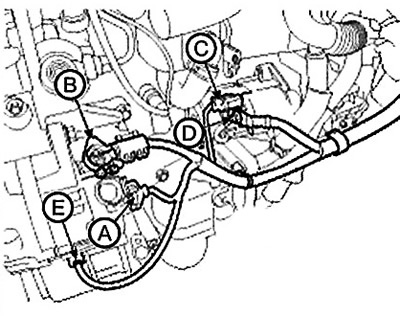
(5) Connect the generator connector (A) and wire (B).
(6) Connect the starter connector (C) and wire (D).
(7) Connect the air compressor switch connector (E).
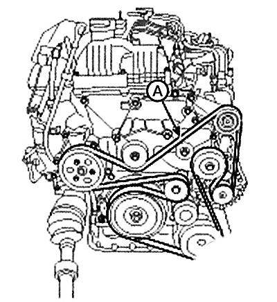
29. Install the drive belt (A).
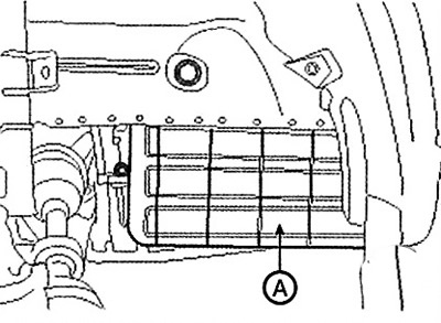
30. Install the side cover (A).
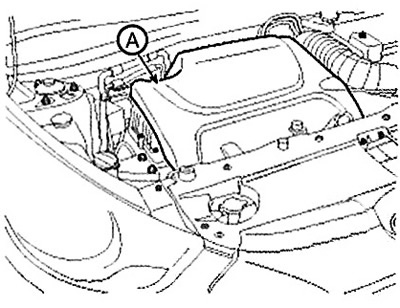
31. Install the engine cover (A).
32. Connect the negative (A) cable to the battery.
Note: Tightening torque: 4.0-6.0 Nm.