Cylinder head
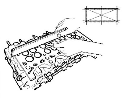
1. Check the non-flatness of the surface of the joint between the cylinder head and the cylinder block and manifolds. To do this, use a special ruler and a set of feeler gauges. Placing the ruler in the planes shown in the figure, measure the non-flatness of the joint surface with feeler gauges.
Note:
Cylinder head gasket surface flatness:
- less than 0.03 mm for width,
- less than 0.09 mm for length,
- less than 0.012 mm/50x50 mm.
Flatness of the mating surface of the collector:
- less than 0.025 mm for width,
- less than 0.160 mm for length.
2. Check the combustion chambers, intake and exhaust ports and the joint surface with the cylinder block for damage. If any defects are found, replace the cylinder head assembly.
Valves, tappets, guides and valve springs
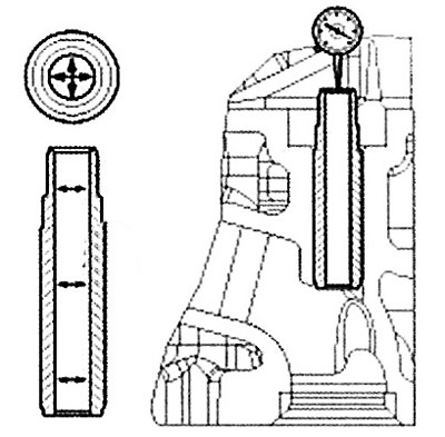
1. Check the technical condition of the guide bushings and valves.
Using a bore gauge, measure the inside diameter of the valve guide as shown in the illustration.
Note:
Standard size of internal diameter:
- Intake: 5.975 - 6.000 mm.
- Exhaust: 5.975 - 6.000 mm.
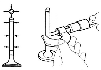
Using a micrometer, measure the outside diameter of the valve stem as shown in the illustration.
Note:
Standard valve outside diameter:
- Intake: 5.933 - 5.953 mm.
- Exhaust: 5.905 - 5.925 mm.
The difference between the inside diameter of the guide bushing and the outside diameter of the valve stem is the valve-to-bushing clearance. If the clearance is greater than the maximum allowable value, the valve and bushing assembly must be replaced.
Note:
Default value:
- Inlet: 0.022 - 0.067 mm.
- Outlet: 0.050 - 0.095 mm.
2. Check the technical condition of the valves:
Check the sharpening angle of the working chamfer of the valve head.
Check the valve surface for excessive wear. If any defects are found, replace the valve with a new one.
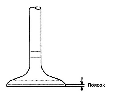
Check the thickness of the valve head band. If the thickness of the valve head band is less than the maximum allowable, the valve must be replaced with a new one.
Note: Standard size of the belt tire:
- Inlet: 1.25mm.
- Outlet: 1.25mm.
Measure the overall length of the valve.
Note:
Standard valve length:
- Intake: 108.3 mm.
- Exhaust: 108.2 mm.
3. Check the technical condition of the valve seats:
Make sure the valve fits snugly on the seat all the way around. Replace the valve seats if necessary.
Before restoring the valve seats, it is necessary to check the technical condition of the valve guide bushings. If any defects are found, it is necessary to replace the bushing and then restore the seat. The thickness of the working surface of the seat contact with the valve must correspond to the standard value.
4. Check the technical condition of the valve springs:
Using a steel square, measure the amount of deviation from the vertical axis of the spring.
Note: The permissible deviation from the vertical axis is 1.571.15 mm.
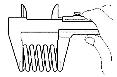
Using a caliper, measure the free length of the spring. If the free length of the spring does not correspond to the standard value, it is necessary to replace the spring with a new one.
Note:
Standard spring length: 44.0 mm.
Length under load:
- 19.9±1.0 kg/36.6 mm.
- 44.1±2.2 kg/27.6 mm.
Camshaft
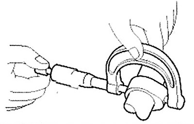
1. Using a micrometer, measure the camshaft lobe height. If the camshaft lobe height is less than the maximum, the camshaft assembly must be replaced.
Note: Standard cam height value:
- Intake: 40.094 mm.
- Exhaust: 40.425 mm.
2. Check the clearance in the camshaft bearings.
Clean and wash the bearing caps and camshaft journals.
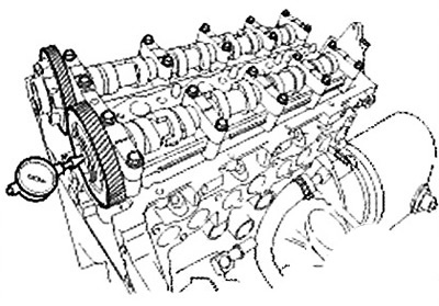
Install the camshafts into the cylinder head.
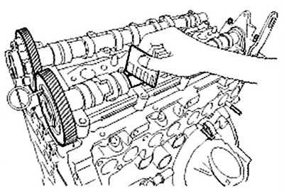
Place special plastic gauges on the camshaft journals as shown in the figure.
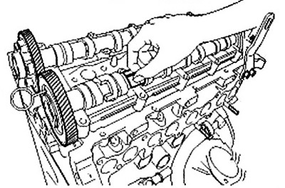
Install the camshaft bearing caps and tighten the bolts to the specified torque.
Note: Tightening torque: 10.0-12.7 Nm.
Caution: Do not turn the camshaft.
Remove the camshaft bearing caps.
Measure the thickness of the plastic gauge (a scale is included with the plastic gauge kit). Determine the amount of clearance in the bearings.
Note: Standard bearing clearance: 0.040 - 0.074 mm.
Note: If the bearing clearance exceeds the permissible limit, the camshaft must be replaced. If necessary, replace the bearing caps or the cylinder head assembly.
Remove the plastic gauges completely.
Remove the camshafts.
3. Measure the axial clearance of the camshaft.
Install the camshafts.
Using a dial indicator, measure the end clearance by moving the camshaft forward/backward.
Note: Standard camshaft axial clearance: 0.05-0.15 mm.
If the axial clearance exceeds the maximum permissible value, it is necessary to replace the camshaft. If necessary, replace the camshaft bearing caps and the cylinder head assembly.
Remove the camshafts.
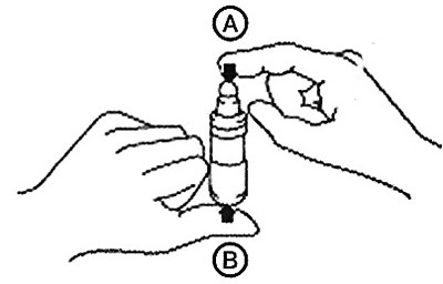
Hydraulic compensators
Hold the hydraulic compensator filled with engine oil by part A and press on part B. If part B moves, replace the hydraulic compensator with a new one.