
Note:
- Wash all parts before installation.
- Always use new cylinder head gaskets and exhaust and intake manifold gaskets.
- Always use new cylinder head bolts.
- Turn the crankshaft clockwise to set the piston of cylinder No.1 to the top dead center (TDC) position.
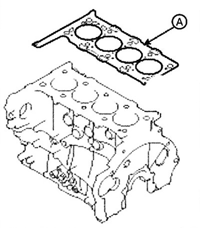
1. Clean the contact surfaces of the cylinder head gasket and block, remove oil, dust and scratches.
2. Select the cylinder head gasket:
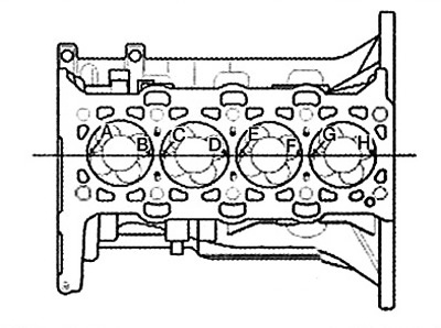
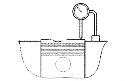
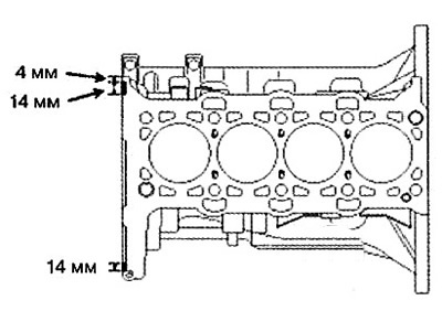
Measure the piston protrusion (at top dead center (TDC)) above the top surface of the cylinder block at eight points (A - H). Measurements should be taken above the crankshaft centerline in the direction of piston movement.
 |
 |
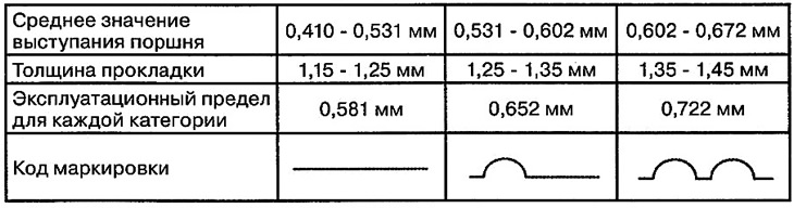
Select a shim from the table below using the average piston protrusion value. Even if just one measuring point has a piston protrusion value outside the range corresponding to the average value, select a shim one size thicker.
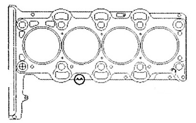
3. Install the cylinder head gasket (A) to the cylinder block.
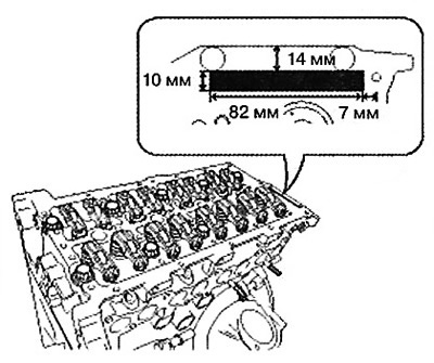
4. Apply sealant to the top surface of the cylinder block, then install the cylinder head gaskets and apply sealant to them:
Apply sealant (LOCTITE 5902 or equivalent) and assemble the cylinder head within 15 minutes.
Install the gasket securely onto the cylinder head.
Be careful not to damage the edges and coating of the cylinder head gasket before and after installation.
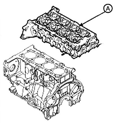
5. Install the cylinder head (A), being careful not to damage the gasket.
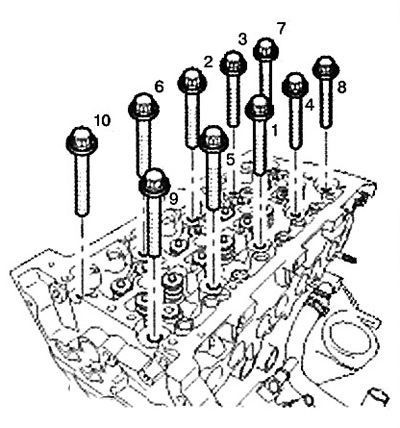
6. Screw in the cylinder head mounting bolts:
Do not apply engine oil to the cylinder head bolts.
Using the special tool (09221-4A000), tighten the 10 cylinder head bolts in the sequence shown in the illustration in several passes.
Note:
- Tightening torque: 78.5 Nm + further tighten by 120° + further tighten by 120°.
- Reuse of cylinder head bolts is not permitted.
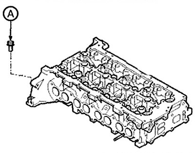
Tighten the cylinder head side bolt (A).
Note: Tightening torque: 30.4 - 34.3 Nm.
7. Install the hydraulic compensator (B) and rocker arm (A):
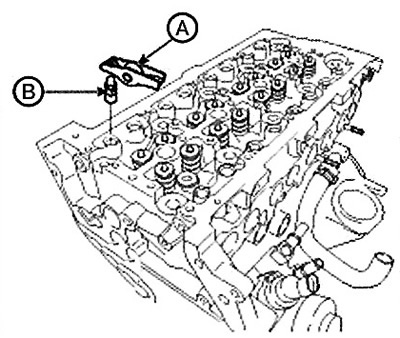
The hydraulic compensator, until its installation, must be stored in a vertical position (to prevent leakage of engine oil) and protected from dust.
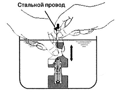
The hydraulic compensator should be installed into the cylinder head carefully so as not to spill oil. In case of oil spillage, it is necessary to release air from the hydraulic compensator as described below:
Dip the hydraulic compensator into the oil 4-5 times, pressing on its cap and at the same time lightly pressing the ball down with a hard steel wire. (To avoid damaging the small ball, do not push the wire too hard.
8. Install the camshaft holder (A) with a new gasket.
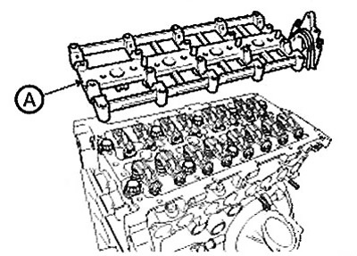
Note: Before installing the camshaft retainer, apply sealant (LOCTITE 518, THREEBOND 1389 or equivalent) to the rectangular area at the rear of the cylinder head.
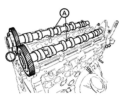
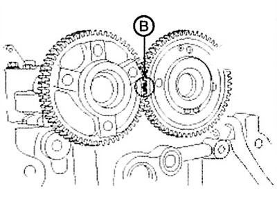
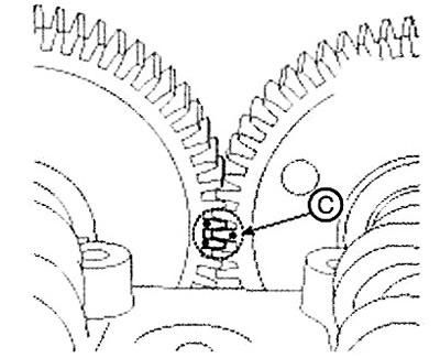
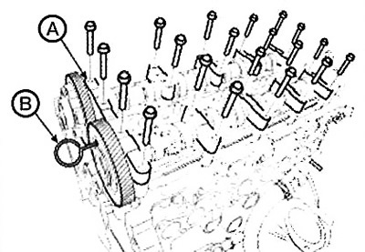
9. Install the camshafts (A) and align the marks (B,C).
Caution: When installing the camshafts, check the front and rear marks on the gears.
In front
Behind
10. Install the camshaft bearing caps (A).
Note: Tightening torque: 10.8-12.7 Nm.
11. Remove the dowel pin (B) (standard power engines only.
Standard power
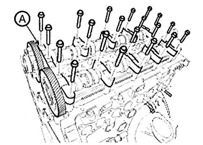
Reduced power
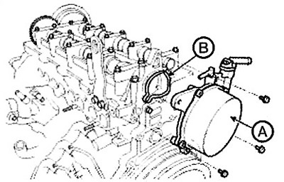
12. Install the vacuum pump (A) with a new O-ring (B).
Caution: Be careful not to lose the sealing ring from the vacuum pump before installing the pump.
Note: Tightening torque: 7.8-11.8 Nm.
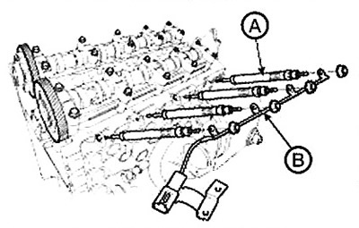
13. Install the glow plugs (A) and connect the wire harness (B) with the plates.
Note: Tightening torque:
- Glow plug: 15 - 20 Nm.
- Plate nut: 0.8 - 1.5 Nm.
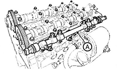
14. Install the fuel rail (A).
Note: Tightening torque: 19.6 - 26.5 Nm.
15. Install the timing chain.
16. Install the intake and exhaust manifolds.