
Note:
- Wash all parts before assembly.
- Before installing parts, apply a thin layer of motor oil to all rubbing surfaces.
- Replace all gaskets, O-rings and seals.
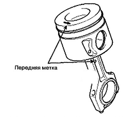
1. Assemble the piston with the connecting rod:
Before pressing in the piston pin, it is necessary to lubricate the surfaces of the pin and connecting rod.
Caution: Be careful not to damage the piston pin when pressing it in.
Using a hydraulic press, press the piston pin into the piston.
Make sure that the piston and connecting rod timing marks are facing the timing chain.
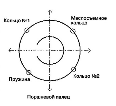
2. Install the piston rings:
Install the oil scraper ring and spring by hand.
Using the special tool, install the two compression rings so that their ends are positioned as shown in the figure (ring #1 should be on the opposite side from ring #2, and the oil scraper ring should be on the opposite side from the spring.)
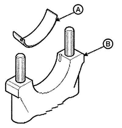
3. Install the connecting rod bearing shells:
Align the protrusion on the bearing shell (A) with the notch on the connecting rod and connecting rod cap (B).
Install the bearing shells into the connecting rod and connecting rod cap as shown in the figure.
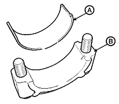
After installing the bearings, apply a coat of engine oil.
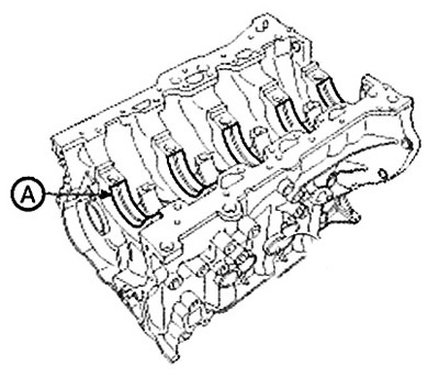
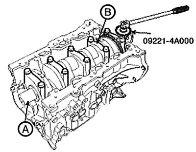
4. Install the crankshaft main bearing shells:
Note: The upper main bearing shells installed in the cylinder block have grooves for supplying engine oil, while the lower shells do not have grooves.
Align the tabs on the bearing shells with the notches on the cylinder block. Install the bearing shells into the five crankshaft bearings (A) as shown in the figure.
Align the tabs on the bearing shells with the notches on the main bearing caps. Install the bearing shells.
After installing the main bearings, apply a coat of engine oil.
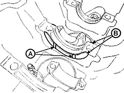
5. Install the thrust bearings on the fourth support. Install 2 thrust bearings (B) on both sides of journal No.4 in the cylinder block so that the oil groove (A) is on the outside.
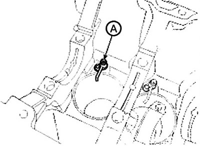
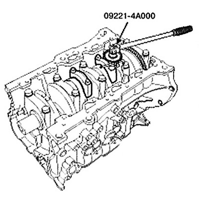
6. Install the oil nozzle (A).
Note: Tightening torque: 8.8-12.7 Nm.
7. Install the crankshaft into the cylinder block.
8. Install the main bearing caps (B) and tighten the cap bolts.
Note:
- Reuse of bearing cap bolts is not permitted.
- Make sure the main bearing caps are installed in the correct order.
- The main bearing cap must be installed with the arrow pointing towards the front of the engine.
- First tighten all main bearing cap bolts to the specified torque, then tighten all bolts to the specified angle.
Apply a thin layer of motor oil to the threaded portion of the lug nuts.
Tighten all bolts to the specified torque in numerical order.
Tighten all bolts to the specified angle in numerical order.
Note: Tightening torque: 49.0 Nm + 120° further.
Make sure the crankshaft turns smoothly.
9. Check the crankshaft axial clearance.
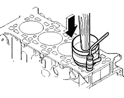
10. Install the pistons together with the connecting rods:
Note: Before installing the pistons into the cylinders, apply a thin layer of engine oil to the ring grooves and cylinder bore.
Install a special device for compressing piston rings. Then install the piston in the cylinder and, using light blows from the wooden handle of the hammer, enter it into the cylinder,
Stop installation when the spring compressor is released. Check that the connecting rod is correctly installed relative to the crankshaft.
Install the connecting rod caps and tighten the mounting bolts.
Note: Tightening torque: 27.5-31.4 Nm + tighten by 88-92°.
Note:
- Reuse of connecting rod cap bolts is not permitted.
- Continue to apply downward force to the piston ring compressor to prevent the rings from expanding before entering the cylinder.
11. Check the axial clearance between the piston and connecting rod.
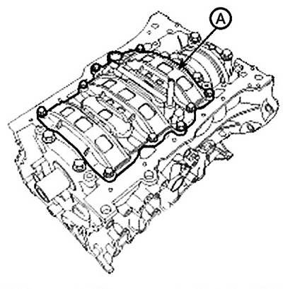
12. Install the ladder frame (A).
Note: Tightening torque: 19.6-26.5 Nm.
13. Install the oil pump module.
14. Install the new rear oil seal housing assembly and encoder:
Install the special tool (09231-1M200, 09231-H110) (A) on the crankshaft.
Press the rear oil seal housing (B) in by hand, then tighten the bolts.
Note: Tightening torque: 9.8-11.8 Nm
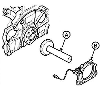
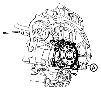
Install the encoder (A).
Attention
- Before installing the rear oil seal housing assembly, apply a layer of engine oil to the seal.
- Be careful not to damage or bend the seal.
- Remove harmful materials from the crankshaft flange and use a special tool to avoid damaging and bending the seal.
- Fully insert the dust cover into the hole in the cylinder block and complete the assembly with the sensor wire.
- Reuse of the rear oil seal housing is not permitted.
- When working with a special tool, avoid its contact with foreign substances.
- When installing the rear oil seal housing, do not hold it by the edge.
15. Install the flywheel (vehicles with manual transmission).
Note: Tightening torque: 117.7- 127.5 Nm.
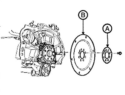
16. Install the drive disc (B) and intermediate plate (A) (vehicles with automatic transmission).
Note: Tightening torque: 117.7-127.5 Nm
17. Install the coolant pump.
18. Install the high pressure fuel pump.
19. Install the cylinder head.
20. Install the timing chain.
21. Install the intake and exhaust manifolds.
22. Remove the engine from the stand.
23. Install the engine assembly with the gearbox.