Note: This procedure does not require engine removal.
Attention.
- To avoid damage to painted surfaces, use protective coatings.
- To avoid damage, disconnect the connectors carefully, holding the connector with your hand.
Note:
- Label all wires and hoses to avoid mistakes when reconnecting.
- Turn the crankshaft pulley and align its groove with the timing mark on the timing chain cover (piston of cylinder No.1 at top dead center of the compression stroke).
1. Disconnect the negative (A) cable from the battery.
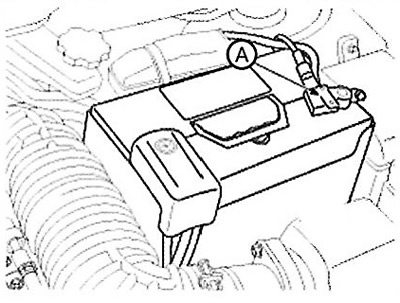
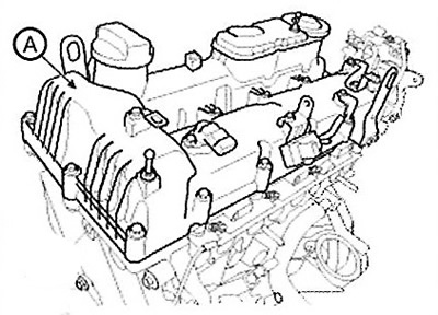
2. Remove the engine cover (A).
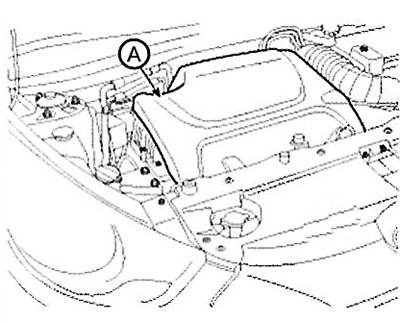
3. Remove the side cover (A).
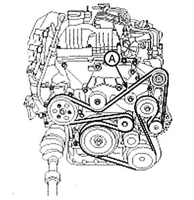
4. Loosen the tensioner by turning it counterclockwise with a wrench. Then remove the drive belt (A).
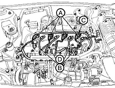
5. Disconnect the engine wire harness connectors and remove the wire harness clamps from the cylinder head cover.
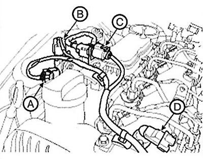
(1) Disconnect the differential pressure sensor connector (A). (With diesel particulate filter).
(2) Disconnect the exhaust gas temperature sensor connector (B). (With diesel particulate filter).
(3) Disconnect the oxygen sensor connector (C).
(4) Disconnect the camshaft position sensor (CMPS) connector (D).
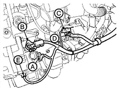
(5) Disconnect the generator connector (A) and wire (B).
(6) Disconnect the starter connector (C) and wire (D).
(7) Disconnect the air compressor switch connector (E).
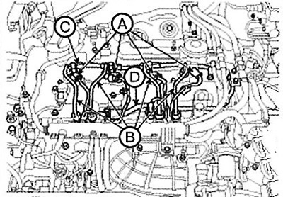
6. Disconnect the injector connectors (A), remove the injectors and disconnect the high pressure pipes (B), fuel return hose (C) and vacuum hose (D) of the exhaust gas recirculation (EGR) system.
Standard power
Reduced power
7. Disconnect the engine ground wire (A).
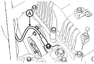
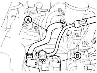
8. Disconnect the breather hose (A).
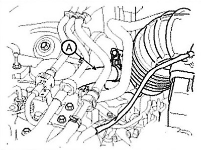
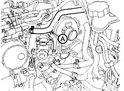
9. Disconnect the vacuum hose (A).
10. Disconnect the power steering oil hose (A) and remove the power steering pump (B). (HPS only).
11. Remove the cylinder head cover (A).
12. Drain the engine oil, then remove the oil filter and oil cooler assembly (A).
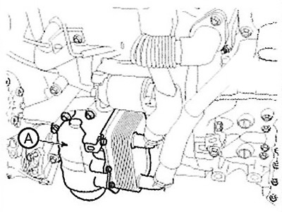
Note: Drain engine oil from the oil filter before removing.
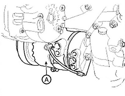
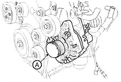
13. Remove the air compressor (A).
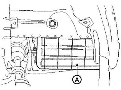
14. Remove the lower oil pan (A).
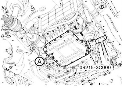
15. Remove the upper oil pan (A).
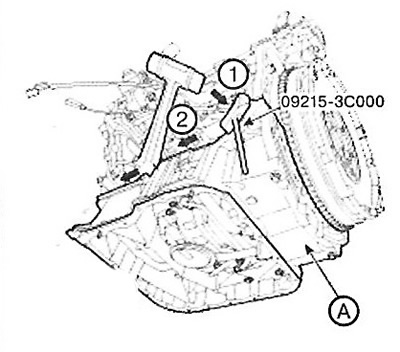
Note: To avoid damaging the surface between the cylinder block and the oil pan, use the special tool (09215-ЗС000) when removing the upper and lower oil pans.
Attention.
- Place the special tool between the oil pan and the cylinder block (or upper oil pan), tapping it lightly with a plastic hammer in the direction of the arrow.
- Lightly tap the special tool with a plastic hammer in the direction of the arrow, go along the edge of the oil pan for at least ⅔ of its length. Then remove the pan from the cylinder block (or upper oil pan).
- Do not turn the special tool without tapping. Doing so may damage the special tool.
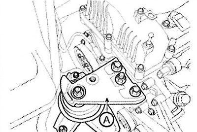
16. Remove the engine mount bracket.
(1) Place a jack under the cylinder block.
Caution: Be careful not to damage the balance shaft and oil pump module.
(2) Remove the engine mount bracket (A).
17. Remove the generator (A).
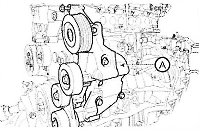
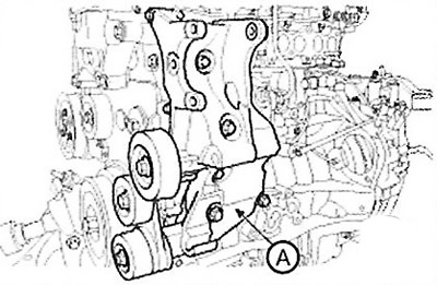
18. Remove the accessory drive system bracket (A) as an assembly.
Type MDPS
HPS type
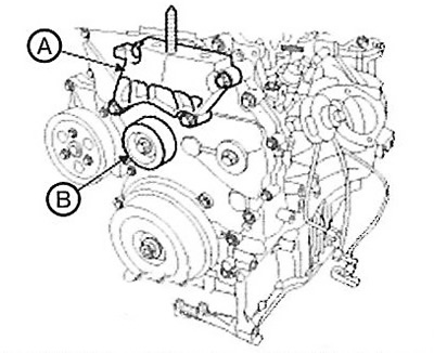
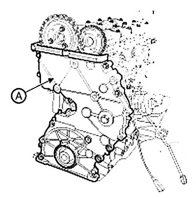
19. Remove the engine support bracket (A) and the drive belt idler roller (B).
20. Set the piston of cylinder No.1 to the top dead center in the compression stroke.
(1) Turn the crankshaft pulley and align its groove with the timing mark on the timing chain cover.
Note: Do not turn the crankshaft counterclockwise.
(2) Check that the timing mark (A) of the exhaust camshaft gear and the timing mark (B) of the intake camshaft gear are aligned as shown in the illustration.
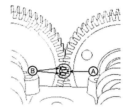
Note: Otherwise, rotate the crankshaft one revolution (360°). (Do not rotate the crankshaft counterclockwise.).
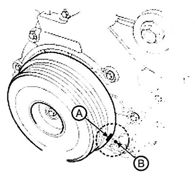
24. Remove the crankshaft vibration damper pulley (A).
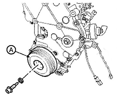
Caution: Do not press the pulley or apply excessive force to avoid deformation of the rubber part.
Note: Loosen the crankshaft pulley bolt, securing the ring gear with a special stopper (09231-2B100) (A), then remove the starter.
22. Remove the timing chain cover (A).
Note: After removing the chain cover and oil pan, carefully remove any remaining sealant and oil from the sealing surface. (Any contamination of the sealing surface may result in subsequent oil leakage despite the application of sealant.).
23. Remove the automatic tensioner (A) of the timing chain "B" and the guide (B).
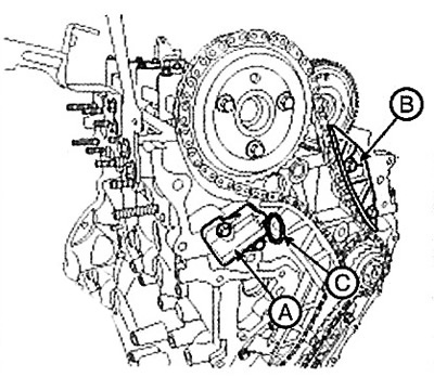
Note: Before removing the automatic tensioner, squeeze it and insert the installation pin (C) (steel wire with a diameter of ∅ 2.5 mm).
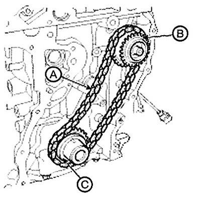
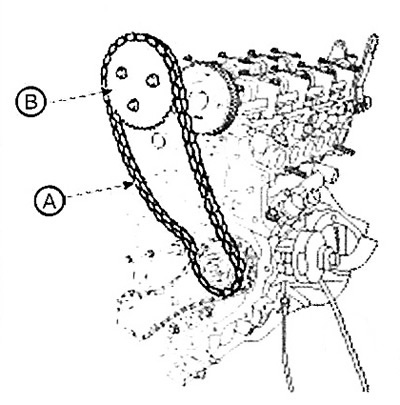
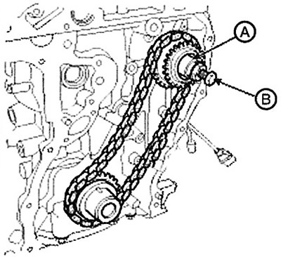
24. Remove the timing chain (A) "B" with the camshaft sprocket (B).
25. Remove the automatic tensioner (A) of the timing chain "A".
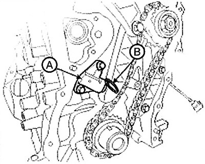
Note: Before removing the automatic tensioner, squeeze it and insert the installation pin (B) (steel wire with a diameter of ∅ 2.5 mm).
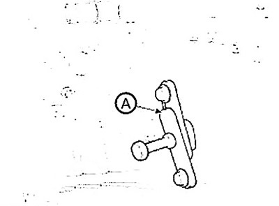
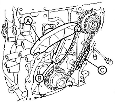
26. Remove the lever (A) of the "B" chain of the gas distribution mechanism drive, the lever (B) of the "A" chain of the gas distribution mechanism drive, and the guide (C) of the "A" chain of the gas distribution mechanism drive.
27. After unscrewing the high-pressure pump sprocket nut, install the sprocket stopper (A) (high-pressure pump puller 09331-1M100).
28. Turn the bolt (B) of the special tool clockwise until the high pressure pump sprocket is pushed out.
29. Remove the timing chain "A" (A) together with the high-pressure fuel pump sprocket (B) and the crankshaft sprocket (C).