Attention.
- To avoid damage to painted surfaces, use protective coatings.
- To avoid damage, disconnect the connectors carefully, holding the connector with your hand.
Note: Mark all hoses to avoid wires and 200 RPM or more use errors when reconnecting.
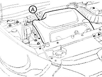
1. Remove the engine cover (A).
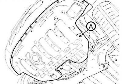
2. Remove the engine protection (A).
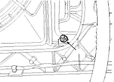
3. Loosen the radiator drain plug (A) and drain the engine coolant. Remove the radiator cap to speed up draining.
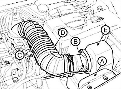
4. Remove the air filter assembly.
(1) Remove the air duct (A).
(2) Disconnect the mass air flow sensor (AFS) connector (B).
(3) Disconnect the breather hose (C).
(4) Disconnect the air intake hose (D) and remove the air cleaner assembly (E).
Note:
Tightening torque:
- Clamps: 2.9-4.9 Nm
- Bolts: 7.8-9.8 Nm
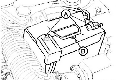
5. Disconnect the battery terminals (A) and remove the battery (B).
Note:
Tightening torque:
- (-) output: 4.0-6.0 Nm.
- (+) output: 7.8-11.8 Nm.
Bracket bolt: 9.8-11.8 Nm.
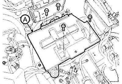
6. Remove the battery tray (A).
Note: Tightening torque: 9.8-11.8 Nm.
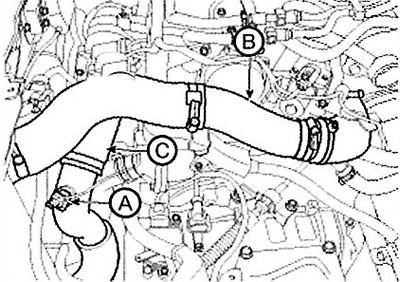
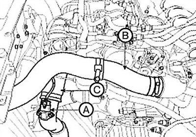
7. Disconnect the intake air temperature sensor connector (A) and disconnect the inlet (B) and outlet (C) pipes and the intercooler hose.
Note:
Tightening torque:
- Clamps: 4.9-6.9 Nm.
- Bolt: 9.8-11.8 Nm.
Standard power
Disconnect the boost pressure sensor (BPS) connector (A) and disconnect the inlet (B) and outlet (C) pipes and the intercooler hose.
Reduced power
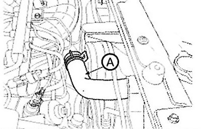
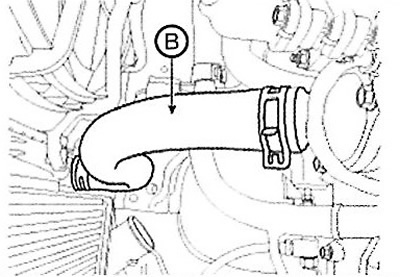
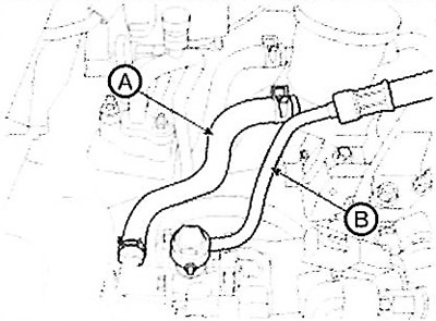
8. Remove the upper (A) and lower (B) radiator hoses.
 |
 |
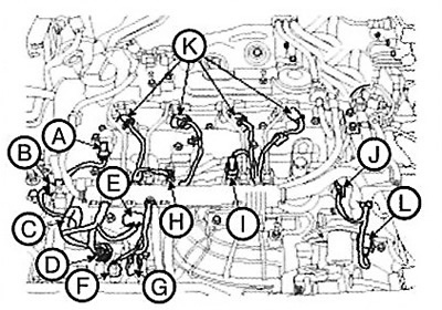
9. Disconnect the engine wire harness connectors and remove the wire harness clamps from the cylinder head cover and intake manifold.
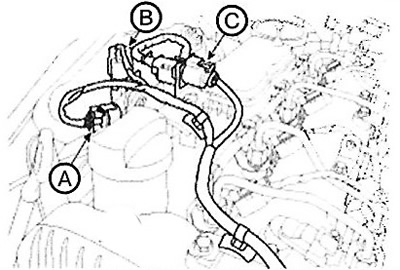
(1) Disconnect the differential pressure sensor connector (A). (With diesel particulate filter).
(2) Disconnect the exhaust gas temperature sensor connector (B). (With diesel particulate filter).
(3) Disconnect the oxygen sensor connector (C).
(4) Disconnect the camshaft position sensor (CMPS) connector (A).
(5) Disconnect the fuel rail pressure sensor connector (B).
(6) Disconnect the glow plug connector (C).
(7) Disconnect the fuel pressure regulator connector (D).
(8) Disconnect the boost pressure sensor (BPS) connector (E). (For standard power engines only.).
(9) Disconnect the oil pressure sensor connector (F).
(10) Disconnect the crankshaft position sensor (CKPS) connector (G).
(11) Disconnect the connector (H) of the exhaust gas cooling (EGR) valve.
(12) Disconnect the fuel temperature sensor connector (I).
(13) Disconnect the fuel rail pressure regulator connector (J).
(14) Disconnect the injector connectors (K).
(15) Disconnect the air supply control valve connector (L).
Standard power

Reduced power
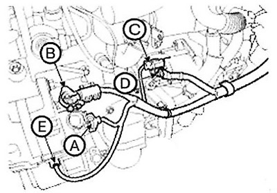
(16) Disconnect the connector (A) of the intake manifold geometry change actuator.
(17) Disconnect the coolant temperature sensor (ECTS) connector (B).
(18) Disconnect the connector (C) of the electric actuator of the variable geometry turbocharger (VGT).
(19) Disconnect the exhaust gas recirculation (EGR) actuator connector (D).
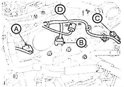
(20) Disconnect the generator connector (A) and wire (B).
(21) Disconnect the starter connector (C) and wire (D).
(22) Disconnect the air compressor switch connector (E).
10. Disconnect the harness connectors, gear shift cable and ground wire.
11. Remove the wire harness protector (A).
12. Disconnect the engine ground wire (A).
13. Disconnect the fuel hoses (A).
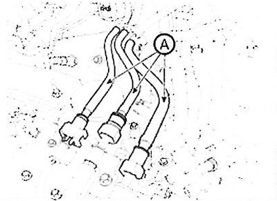
Standard power
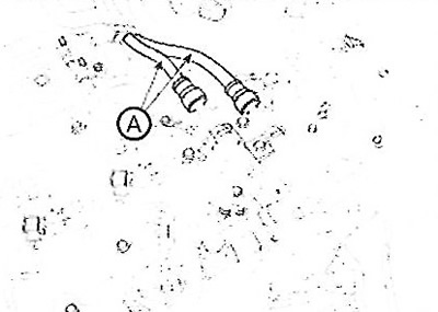
Reduced power
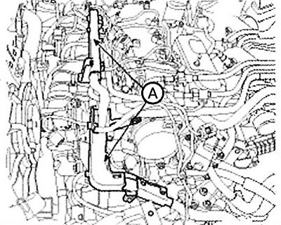
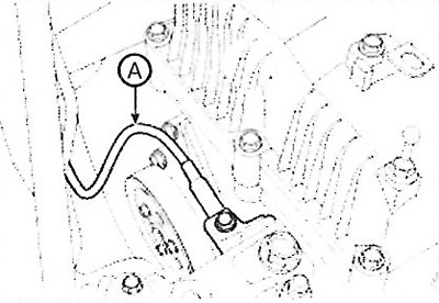
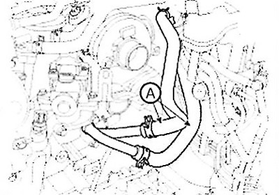
14. Disconnect the vacuum hose(A).
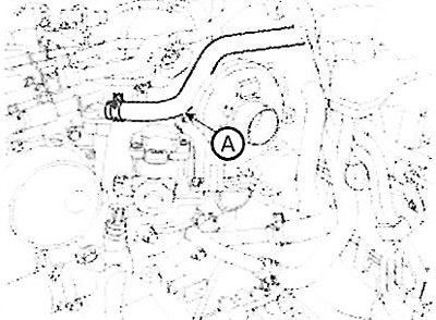
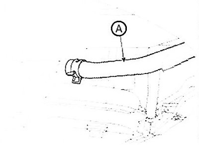
15. Disconnect the heater hoses (A).
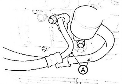
16. Disconnect the power steering oil hose (A). (HPS only)
 |
 |
17. Drain the refrigerant, disconnect the high and low pressure pipes (A) of the air compressor.
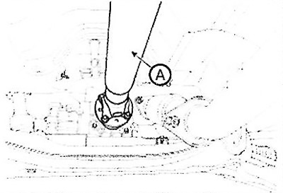
18. Remove the driveshaft (A).
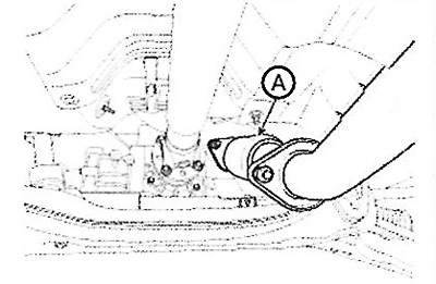
19. Remove the front muffler (A).
Note: Tightening torque: 39.2-58.8 N·m.
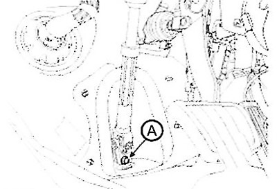
20. Loosen the bolt (A) securing the steering shaft universal joint.
21. Remove the front wheels.
22. Remove the shock absorbers, stabilizer rods, lower arm ball joints and steering rod ends.
23. Remove the drive shaft from the hub.
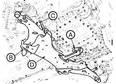
24. Support the subframe with a jack, then unscrew the bolt (A) securing the rear roller support bracket, the bolts (B) securing the subframe, unscrew the nuts (C) and remove the subframe (D).
Note: Tightening torque:
- Bolt (A): 107.9-127.5 Nm.
- Bolts (B), nuts (C): 156.9-176.5 Nm.
25. Support the engine with a jack.
Note:
- Make sure that the power unit is securely supported with a jack, otherwise the power unit may fall after unscrewing the bracket mounting bolts.
- Before removing the power unit, make sure that all hoses and connectors are disconnected from it.
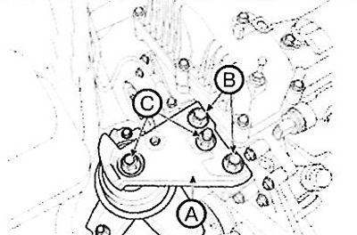
26.Remove the engine support bracket (A).
The original can be read on the resource: HyundaiBook.ru
Note: Tightening torque: Bolts (B), nuts (C): 63.7 - 83.4 Nm.
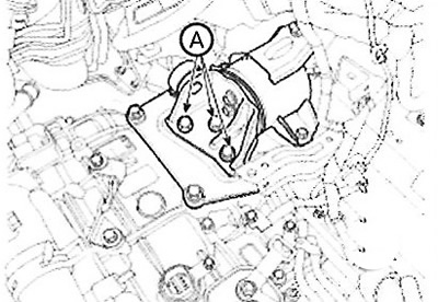
27. Remove the bolts (A) of the gearbox support bracket.
Note: Tightening torque: 88.3-107.9 Nm.
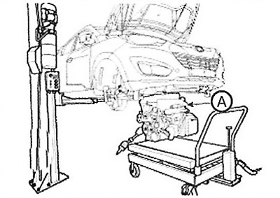
28. Remove the power unit (A) by raising the vehicle.
Caution: When removing the engine and transmission assembly, be careful not to damage surrounding components or the body.