
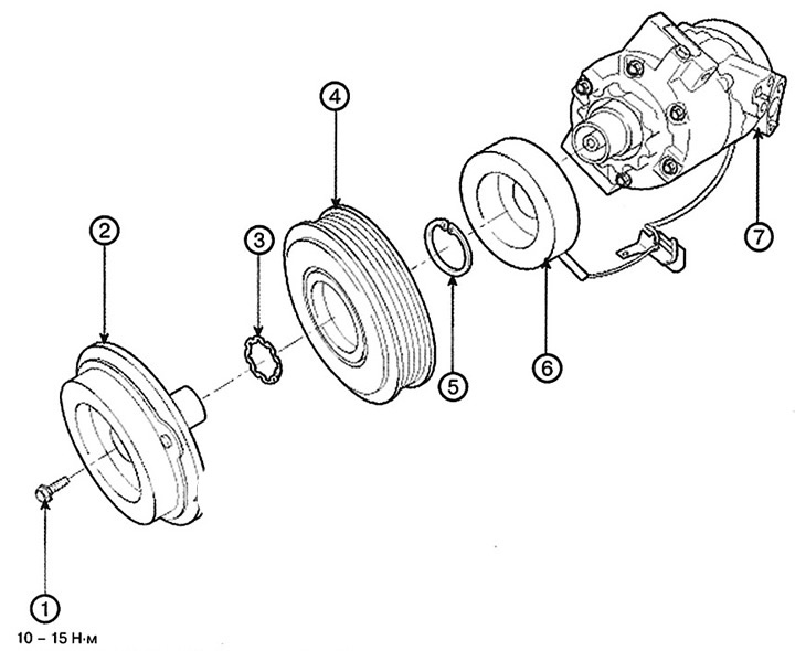
1. Bolt
2. Disc and hub assembly
3. Snap ring (pulley)
4. Pulley
5. Retaining ring (excitation coils)
6. Excitation coil
7. Compressor assembly
Removal
1. If the compressor is partially open, run the engine at idle speed and turn on the air conditioning system for a few minutes, then turn off the engine.
2. Disconnect the negative terminal from the battery.
3. Extract the refrigerant using a recovery and recharging machine.
4. Loosen the drive belt.
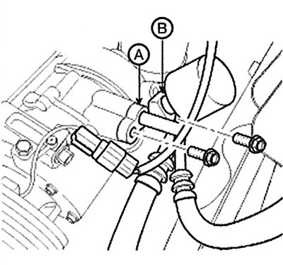
5. Loosen the bolts, then disconnect the inlet (A) and outlet (B) lines from the compressor. Plug or close the lines immediately after disconnecting them to prevent atmospheric moisture and dust from entering them.
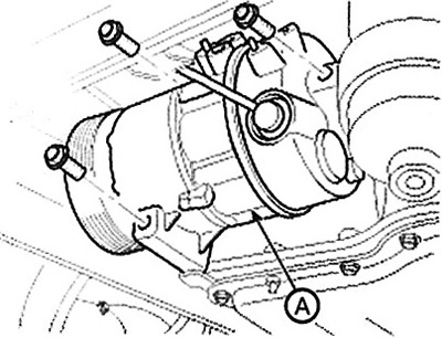
6. Disconnect the compressor clutch connector, unscrew the 3 mounting bolts and remove the compressor (A).
The basis of the material is information from the website (www.HyundaiBook.ru)
Installation
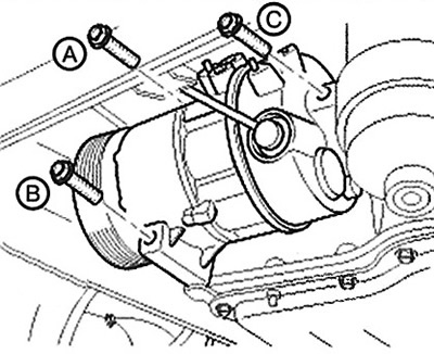
1. Check the length of the compressor mounting bolts, then tighten them in order A->IN->WITH.
Note: Tightening torque: 20.0 - 32.9 Nm.
2. Installation is performed in the reverse order of removal. Please note the following features:
When installing a new compressor, drain all refrigerant oil from the old compressor and measure its volume. Subtract the volume of oil drained from 120 cc to obtain the volume of oil that must be drained from the new compressor (via the inlet connector).
Replace the sealing rings with new ones; apply a thin layer of refrigerant oil to them before installation. Be sure to use O-rings designed for R-134a refrigerant to prevent leaks.
To avoid contamination, do not pour drained oil back into the container, never mix it with other oils.
Immediately after using the oil, place the lid on the container and tighten it tightly to prevent moisture from getting in.
Do not allow coolant oil to come into contact with the vehicle's surfaces, as this may damage the paintwork. If coolant oil comes into contact with a painted surface, it must be washed off immediately with water.
Adjust the drive belt tension.
Prime the system and check its performance.
Checking the technical condition
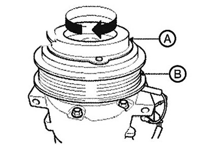
1. Inspect the galvanized parts of the disc and hub assembly (A) for discoloration, peeling or other damage. If damaged, replace the clutch assembly.
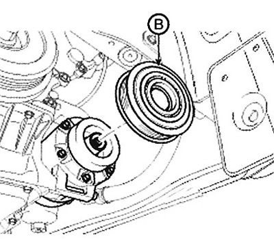
2. Check the pulley bearings (B) for play and binding by rotating the pulley by hand. If there is excessive play/binding or noise, replace the clutch assembly.
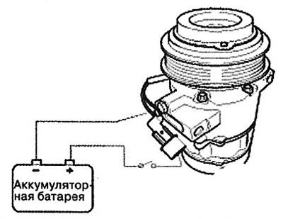
3. Check the operation of the magnetic clutch. Connect the compressor terminals to the positive (+) terminal of the battery, and the compressor body to the negative (-) terminal. Check the noise generated by the clutch operation.
Disassembly
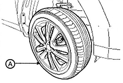
1. Remove the front left wheel (A).
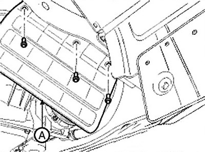
2. Remove the engine side cover (A).
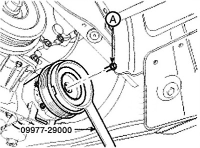
3. Loosen the center bolt (A) while holding the disc and hub assembly with a special tool (09977-29000).
Note: Tightening torque: 10-15 Nm.
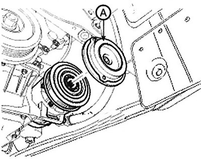
4. Remove the disc and hub assembly (A) and the adjusting shims (clearance adjusting washers). Do not lose these shims.
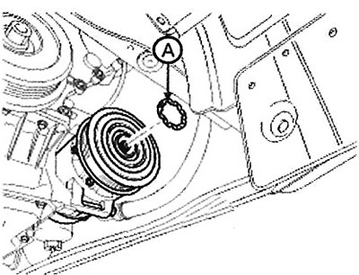
5. Remove the snap ring (A), then remove the pulley (B).
Note:
Be careful not to damage the pulley (B) and compressor during removal/installation.
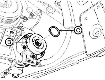
The removed retaining ring (A) must be replaced with a new one.
 |
 |
6. Remove the retaining ring (B), then remove the excitation coil (C). Be careful not to damage the coil and the compressor.
7. Install the compressor clutch in the reverse order of removal. Please note the following features.
A. Clean the moving surfaces of the pulley and compressor with a non-petroleum based solvent.
B. Install new snap rings, making sure they are seated correctly in the groove.
C. After assembling the pulley, make sure it rotates smoothly.