
Contents: Precautionary measures ⇓ Module (DAB, RAV, SAB) ⇓ Driver's airbag and coil wire ⇓ Front passenger airbag ⇓
Cars are equipped with an additional safety system (SRS – Supplemental Restrain System), better known as airbags. The system consists of sensors installed on the front side of the vehicle, airbags and a control and diagnostic unit. The vehicle is equipped with an HAE–3 airbag system. The HAE–3 system can be installed in various versions: DAB 2BPT, DAB PAB 2BPT, DAB PAB 2BPT 2FSAB (DAB – driver's airbag, PAB – front passenger airbag, BPT – seat belt tensioner, FSAB – side airbag).
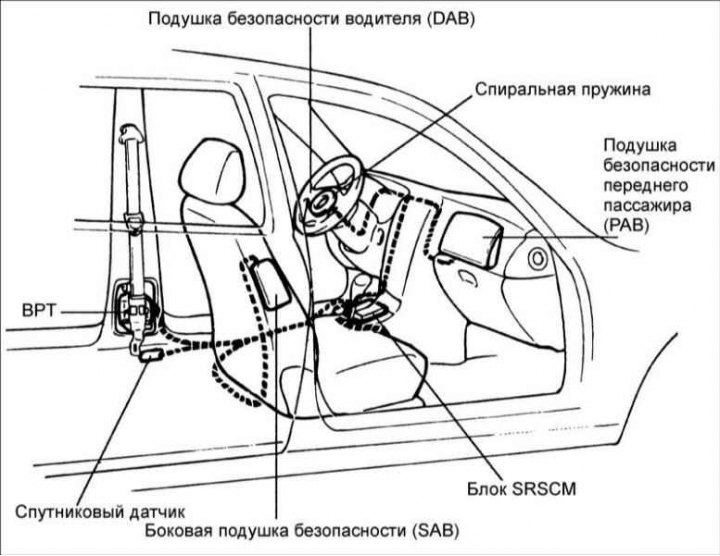
The SRS consists of: a driver-side air chamber located in the center of the steering wheel and containing a folded airbag and a gas generator unit; an air chamber on the front passenger side, located in the instrument panel and containing a folded airbag and a gas generator unit; side air chambers located in the backrests of the driver and front passenger and containing folded cushions and a gas generator unit.
The SRSCM control unit is located on the floor of the vehicle under the heater core and controls the airbag system and includes: an accelerometer that detects vehicle deceleration; a spiral wire (spring) located in the steering column; electrical circuits and connectors; knee buffer located under the steering column. The coiled wire transmits the signal regardless of the position of the steering wheel.
The SRSCM unit determines the moment of impact based on information from the accelerometer, which constantly monitors the vehicle's acceleration.
The airbag deploys during a frontal or near-frontal collision with moderate to severe force.
The pyrotechnic gas generator converts the control electrical signal into an ignition signal, which causes the powder to decompose, inflating the airbag bag.
Only trained personnel should be allowed to service airbags or SRS components. When servicing the SRS, extreme caution must be exercised to avoid injury to personnel due to unauthorized deployment of the driver or front passenger air bags.
Precautionary measures
If the airbag system is not switched off or maintained correctly, the airbags may be deployed without authorization and serious personal injury may result. Also, improper maintenance of the airbag system may result in the airbag not deploying in a collision.
Before performing any maintenance, including removing or installing system components, carefully follow these guidelines.
1. Before servicing the air bag system, make sure that at least 30 seconds have passed after the ignition has been turned off and the negative battery cable has been disconnected. The airbag system is equipped with an emergency power source that allows the airbags to deploy if the wires to the battery are disconnected during an accident. The time during which the emergency energy source supplies energy to the airbag system is 150 ms.
2. When the wire from the negative terminal of the battery is disconnected, the memory of the clock and sound systems is erased. Before you begin, extract information from the sound systems. Once the work is completed, set the clock and reinstall the sound systems.
3. Symptoms of air bag system failure are difficult to verify, so diagnostic codes become the most important source of information when troubleshooting.
4. When troubleshooting the air bag system, check the fault codes stored in the memory before disconnecting the battery.
5. Do not use spare airbag parts from other vehicles.
6. Do not disassemble or repair air bag system components.
7. If any SRS component has been dropped or has cracks, dents or other defects in the housing, bracket or connector, replace them with new ones.
8. After completing the work, check the airbag system.
In some cases, the air bag warning light circuit may be compromised by another circuit fault. Therefore, if the air bag warning light is constantly on, check that all DTC codes are cleared from the memory.
9. When carrying out electric welding work, be sure to disconnect the wire from the negative terminal of the battery.
Module (DAB, RAV, SAB)
DAB modules (driver airbag), RAV (front passenger airbag), DSAB (driver's side airbag) and PSAB (passenger side airbag) consist of an opening device and a cushion. Opening device (gas generator) located in the airbag. When a frontal collision occurs with sufficient force to short the SRSCM, current begins to flow through the air bag deployment circuit. This current ignites the gas generator charge and the airbag deploys.
1. When removing an airbag or working with a new airbag, it must be positioned so that the surface of the airbag faces upward. In this case, the locking lever of the double-locking connector must be in the locked position.
2. Never measure the resistance of the airbag squib as this may cause it to deploy.
3. Store airbags at a temperature no higher than 93°C, away from humidity and electrical interference.
4. When using electric welding, disconnect the connectors from the airbag before starting work.
SRS Wiring Harness
The SRS harness is located inside a yellow tube, which is different from the harnesses of other systems. The connectors on the DAB, PAB, DSAB, PSAB and BPT sides have jumpers that close the electrical circuits when the connectors are disconnected, preventing unwanted airbag deployment.
SRSCM warning light
The SRS indicator lamp located in the instrument cluster is controlled by the SRSCM.
Under certain fault conditions, the SRSCM cannot function and thus cannot control the operation of the indicator lamp. In these cases, the lamp is directly activated by the corresponding circuit, which operates independently of the SRSCM.
1. If there is no voltage supplied to the SRSCM, the lamp remains lit continuously.
2. If there is no internal working voltage, the lamp lights up continuously.
3. If the SRSCM is not connected, the lamp is turned on through the jumper in the wire harness connector.
Spiral spring
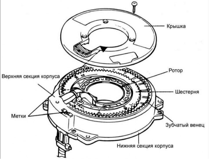
The spiral spring consists of two twisted coils. It is installed between the steering column and the steering wheel and allows the steering wheel to rotate while maintaining contact with the electrical circuit of the safety system at all times.
The steering wheel must be properly installed on the steering column with the coil spring set to neutral position, otherwise a broken wire or other malfunction may occur.
Driver's airbag and coil wire
Removal
1. Disconnect the cable from the negative terminal of the battery.
Warning: Before servicing the airbag system, make sure that at least 30 seconds have passed after the ignition has been turned off and the negative battery cable has been disconnected.
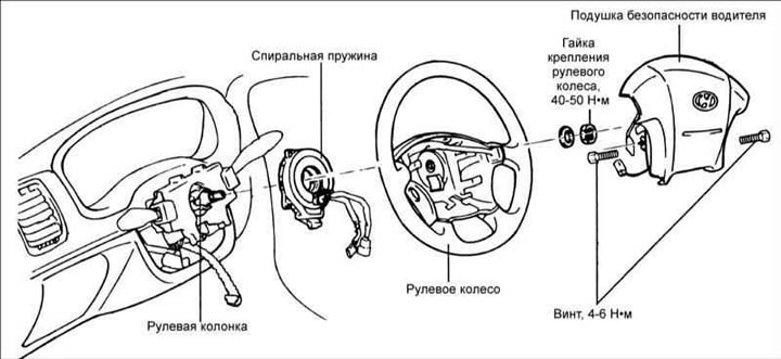
2. Remove the steering wheel cover and use an Allen key to align the driver's airbag mounting bolts.
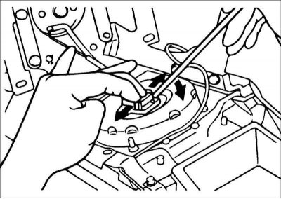
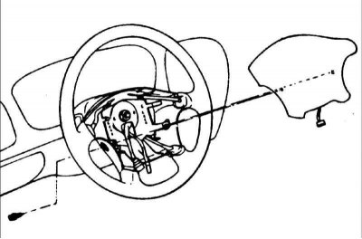
3. When disconnecting the airbag coil wire electrical connector, install the locking device on the connector facing outward.
Warning: Do not use excessive force when disconnecting the coil wire electrical connector from the airbag.
4. Remove the driver's airbag.
Warning: The removed airbag must be stored in a clean, dry place, with the front side facing up.
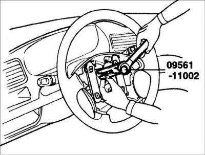
5. Using puller 09561–11002, remove the steering wheel.
The full version is located on the website: hyundaibook.ru
Do not hit the steering wheel as this may damage the steering column protection mechanism and reduce the driver's protection in a frontal collision.
Checking the airbag
If there are any defects, the airbag must be replaced.
Warning! Do not attempt to measure the resistance of the airbag inflator circuit, as this may result in unauthorized deployment of the driver's airbag.
1. Check the airbag cover for dents, cracks or deformation.
2. Check the airbag for dents, cracks or deformation.
3. Check the condition of the hooks and connectors for damage, oxidation of the connector contacts and damage to the wiring harness.
4. Inspect the airbag inflator housing for dents, cracks or deformation.
5. Place the airbag on the steering wheel to check alignment and fit.
Checking the spiral wire (spring)
1. If there are any defects, the spiral wire must be replaced.
2. Check the electrical connectors and yellow protective tube for damage and oxidation of the connector contacts.
Front passenger airbag
Removal
1. Do not disassemble or repair any airbag system components.
2. If the air bag has been dropped or exposed to water, grease or oil, or if there are cracks, dents or other defects in the housing or connector, replace the air bag.
3. The removed airbag must be stored in a clean, dry place, with the front side facing up. Do not place any objects on the airbag that could cause serious injury if the airbag deploys.
4. Do not expose the airbag to temperatures above 93°C.
5. The undeployed airbag unit must be positioned only in accordance with the prescribed procedures.
6. Do not attempt to measure the resistance of the airbag inflator circuit, as this may result in unauthorized deployment of the driver's airbag.
7. After the airbag has been deployed, it must be replaced along with the wire that was exposed to the gases of the pyrotechnic gas generator.
Procedure
1. Disconnect the cable from the negative terminal of the battery.
Warning: Before servicing the airbag system, make sure that at least 30 seconds have passed after the ignition has been turned off and the negative battery cable has been disconnected.
2. Remove the glove box.
3. Disconnect the airbag electrical connector.
4. Remove the instrument panel and airbag.
5. The outer layer of the front passenger airbag is integrated with the instrument panel, so when the airbag deploys, the instrument panel must be replaced.