
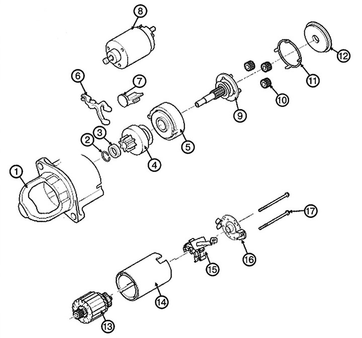
1. Front body
2. Retaining ring
3. Emphasis
4. Overrunning clutch
5. Internal gear
6. Lever
7. Lever seal
8. Magnetic switch
9. Planetary gear shaft
10. Planetary gear
11. Compaction
12. Lid
13. Anchor
14. Body
15. Brush holder
16. Rear body
17. Tie bolt
Replacement
1. Disconnect the negative cable from the battery.
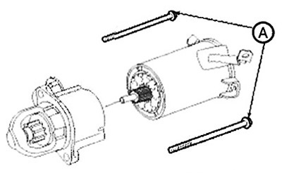
2. Disconnect the starter wire (A) from the terminal "B" (B) of the solenoid (C), and then the connector (D) from the terminal "S" (E).
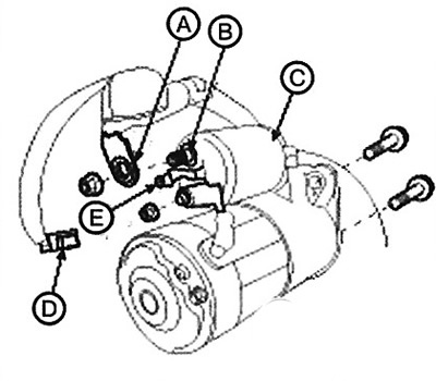
3. Loosen the two starter mounting bolts, then remove the starter.
Note: Tightening torque: 42.2 - 53.9 Nm.
4. Installation is carried out in the reverse order of removal.
Disassembly and assembly
1. Disconnect the "M" terminal (A) from the magnetic switch (B).
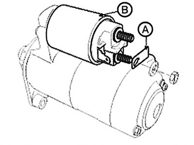
2. Remove the three screws (A), then detach the magnetic switch (B).
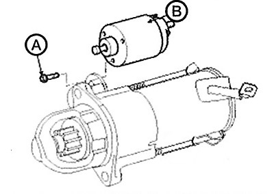
3. Loosen the tie bolts (A).
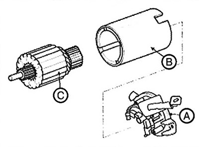
4. Remove the brush holder (A), housing (B) and armature (C).
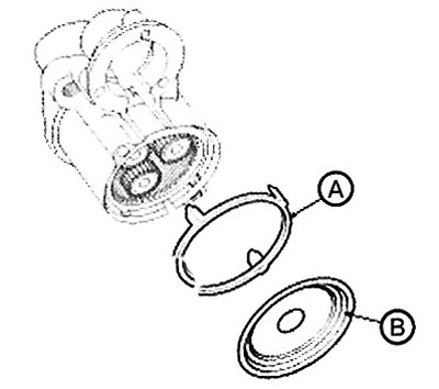
5. Remove the seal (A) and cover (B).
6. Remove the plate (A) and seal (B) of the lever.
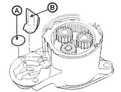
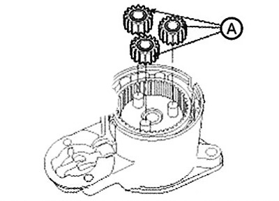
7. Remove the planetary gears (A).
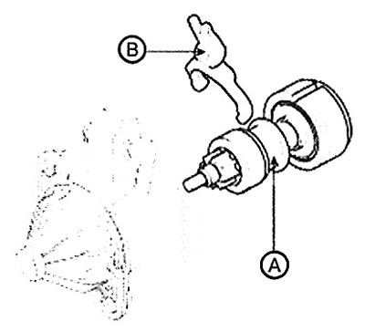
8. Disconnect the planetary gear shaft (A) assembly and lever (B).
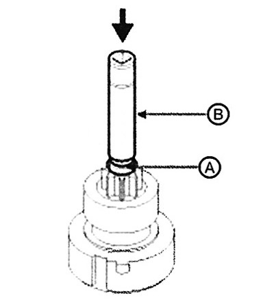
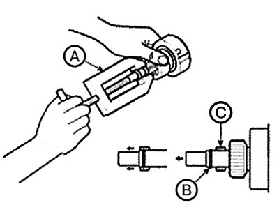
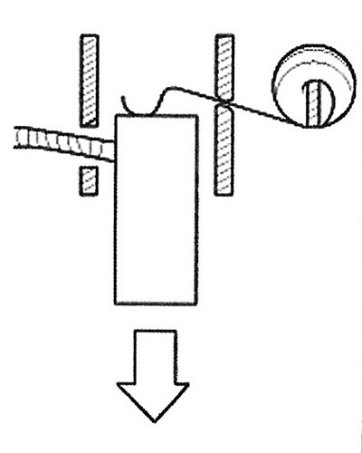
9. Press the retaining ring (A) using the drift (B).
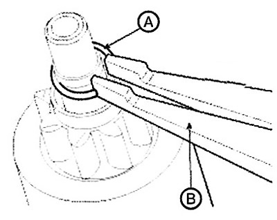
10. Remove the retaining ring (A) using the special tool (B).
11. Remove the stop (A), overrunning clutch (B), internal gear (C) and shaft (D).
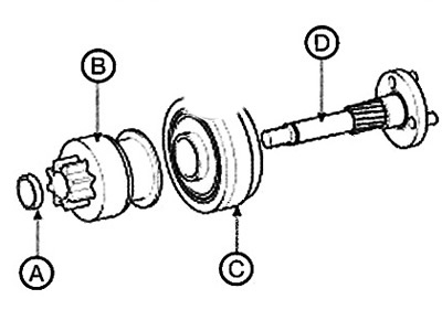
12. Assembly is carried out in the reverse order of disassembly.
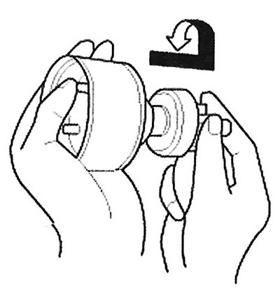
Note: Using a suitable puller (A), install the overrunning clutch retaining ring (B) through the stop (C).
Checking the technical condition
Anchor
1. Remove the starter.
2. Disassemble the starter (see above).
3. Inspect the anchor for wear and damage due to contact with the permanent magnet. If signs of wear or damage are found, replace the anchor with a new one.
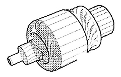
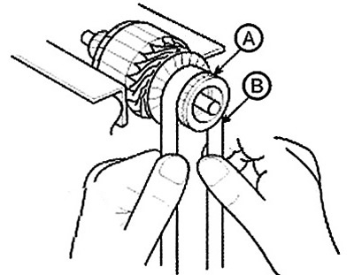
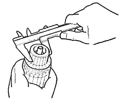
4. Inspect the surface of the commutator (A). If the surface is dirty or burnt, sand it or machine it to the size specified below, or polish it with #500 or #600 sandpaper (B).
5. Check the commutator diameter. If the diameter is less than the maximum permissible value, replace the anchor with a new one.
Note:
Commutator diameter:
Petrol engines:
- Standard value: 27.1mm.
- Maximum permissible value: 26.9 mm.
Diesel engines:
- Standard value: 33.0 mm.
- Maximum permissible value: 27.1 mm.
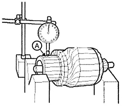
6. Measure the commutator runout (A). If the commutator runout is within the maximum permissible value, check the commutator for carbon dust and brass filings between the plates. If the commutator runout is not within the maximum permissible value, replace the anchor with a new one.
Note:
Commutator beating:
- Standard value: 0.05 mm.
- Maximum permissible value: 0.08 mm.
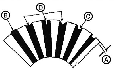
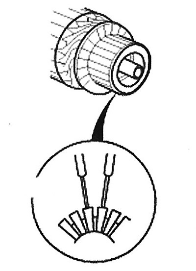
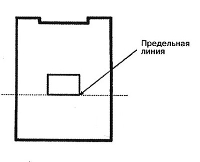
7. Check the depth of the grooves (A) between the commutator plates. If the height of the grooves is too great (B), trim it to the required depth with a hacksaw blade. All grooves (C) between the commutator segments must be trimmed. The slots must not be too thin, concave or V-shaped (D).
Note:
Groove depth:
Petrol engines:
- Standard value: 0.8 mm.
- Maximum permissible value: 0.2 mm.
Diesel engines:
- Standard value: 0.5 mm.
- Maximum permissible value: 0.2 mm.
8. Check the electrical conductivity between the commutator plates. If there is a break in the circuit between any plates, replace the anchor with a new one.
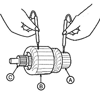
9. Using an ohmmeter, check for continuity between the commutator (A) and the armature coil core (B), and between the commutator and the armature shaft (C). If there is continuity, replace the armature with a new one.
Starter brushes
10. Worn or oily brushes must be replaced with new ones.
Starter brush holder
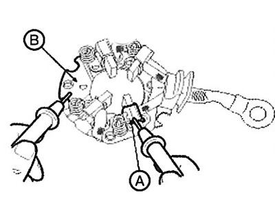
11. Check that there is no continuity between the brush holder (+) (A) and the plate (-) (B). If there is continuity, replace the brush holder with a new one.
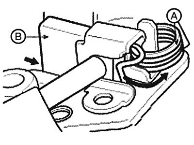
12. Compress the spring (A) of each brush with a screwdriver, then position the brush (B) so that it protrudes halfway from the holder. Release the spring so that it holds the brush.
13. Install the anchor into the housing, then install the brush holder. Compress the spring of each brush again and lower the brush to install it opposite the commutator. Release the spring toward the edge of the brush.
Note: To install new brushes, place #500 or #600 sandpaper between the commutator and each brush, grit side up, and rotate the armature gently. The contact surface of the brushes will be filed down to the contour of the commutator.
Overrunning clutch
14. Move the overrunning clutch along the shaft. If the clutch does not move smoothly, replace it with a new one.
15. Try to turn the overrunning clutch in both directions. If the clutch does not lock in one direction or locks in both directions, replace it with a new one.
16. If the drive pinion is worn or damaged, replace the overrunning clutch (the pinion is not supplied as a separate spare part). If the teeth of the starter drive pinion are damaged, check the condition of the flywheel and torque converter ring gear.
Cleaning
1. Do not immerse parts in cleaning solvent. Immersion of the armature in solvent will damage the insulation of the wiring. These parts are only allowed to be wiped with a cloth.
2. Do not immerse the overrunning clutch in cleaning solvent. It contains factory grease.
3. The drive may be cleaned with a brush soaked in a cleaning solution, after which the drive must be wiped dry with a cloth.