
Removal
Caution: Before removing the drive shafts, cover all sharp edges near the drive shafts with towels to protect the covers from damage.
Caution: When removing the drive shaft, be careful not to stretch the constant velocity joint, as this may cause the internal components of the joint to separate and possibly cause damage. The CV joint and protective boot must be properly protected when working on or near drive shafts.
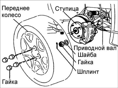
1. Remove the front wheel.
2. Remove the cotter pin, unscrew the castle nut and remove the washer securing the drive shaft to the front wheel hub.
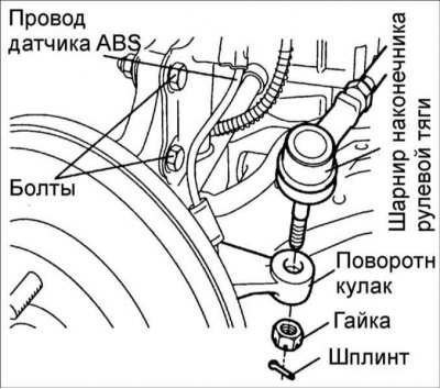
3. Remove the cotter pin and unscrew the nut securing the ball joint journal of the steering rod end to the steering knuckle. Using puller 09568–34000, press the ball joint pin out of the steering knuckle.
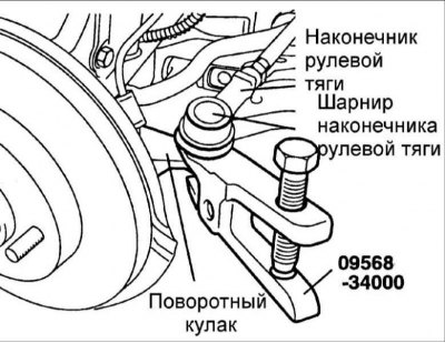
Caution! Use a cord to secure the puller to the nearest element of the vehicle.
4. Remove the caliper and secure it to the front strut with soft wire.
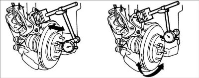
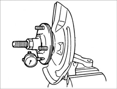
5. Using a dial indicator, measure the runout and axial clearance of the front wheel hub.
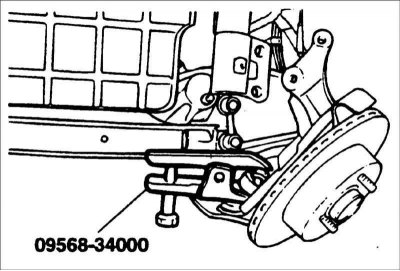
6. Using puller 09568–34000, disconnect the lower arm ball joint from the steering knuckle.
7. Remove the speed sensor from the steering knuckle.
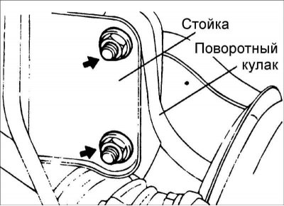
8. Mark the position and remove the bolts securing the lower part of the front suspension strut to the steering knuckle.
9. Use a nylon hammer to knock the drive shaft out of the front wheel hub. If the drive shaft is a tight fit in the front wheel hub, spray penetrating aerosol solvent into the spline area and then re-tighten the flange nut until it is flush with the end of the shaft. Using a brass hammer, tap the nut to knock the drive shaft out of the hub.
10. Remove the steering knuckle together with the front wheel hub.
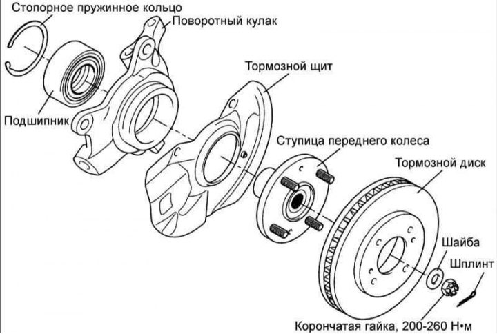
Disassembly
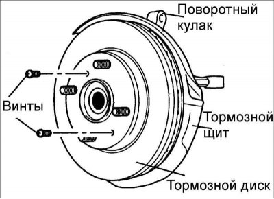
1. Remove the two screws and remove the brake disc from the front wheel hub.
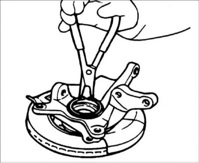
2. Remove the snap ring.
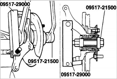
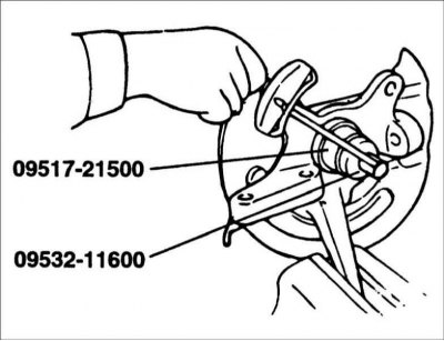
3. Install special tools 09517-29000, 09517-21500 as shown in the figure.
4. Using the special tool, remove the front wheel hub from the steering knuckle.
5. Remove the special tool and dust ring.
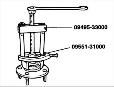
6. Using special tool 09495–33000, 09551–31000, remove the inner bearing race from the hub.
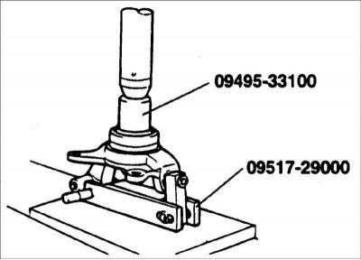
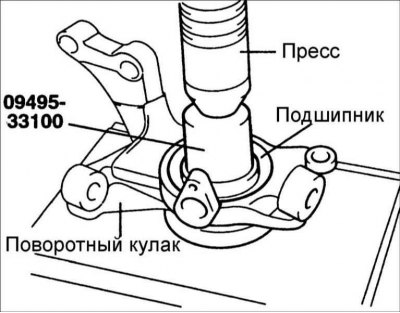
7. Using special tool 09495–33100, 09517–29000, remove the outer bearing race from the steering knuckle.
Examination
1. Check the hub for cracks and wear.
2. Check the brake disc for wear or damage.
3. Check the steering knuckle for cracks.
4. Check the bearing for cracks or damage.
Assembly
1. Apply a thin coat of grease to the steering knuckle bore and to the outer bearing race.
2. Using a press with a mandrel 09495–33100 of the appropriate diameter, press in a new wheel bearing.
- Do not apply press force to the bearing inner race.
- Always use a new bearing when installing.
3. Install the spring ring into the groove of the steering knuckle.
4. Install the dust ring.
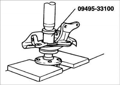
5. Using a press with a mandrel 09495–33100 of the appropriate diameter, press the hub into the wheel bearing.
Caution: Do not apply press force to the outer bearing ring.
6. Install the brake shield.
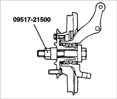
7. Using special tool 09517–21500, screw the hub to the steering knuckle, tightening the tool bolt to a torque of 200–260 N·m.
8. Turn the hub several times to ensure that the bearing elements are seated in their proper places.
9. Measure the torque required to turn the bearing. Torque: no more than 1.8 Nm.
10. If the torque is 0 Nm, measure the axial play of the hub bearing.
11. If the torque exceeds the required value, then the bearing is not installed correctly in the steering knuckle and on the hub. Disassemble the steering knuckle and reassemble it. Bearing axial play: no more than 0.008 mm.
The article is borrowed from an online resource hyundaibook.ru
12. Remove special tool 09517–21500.
13. Install the brake disc and secure it with screws.
Installation
1. Installation is carried out in the reverse order of removal.
Caution! Tighten the threaded connections to the required torques in the following order:
- Drive shaft mounting nut: 200–260 N·m
- Lower arm ball joint trunnion nut to steering knuckle: 60–72 N·m
- Steering knuckle to strut nut: 130–150 N·m
2. Install the strut and drive shaft into the steering knuckle.
3. Connect the ABS sensor.
4. Install the caliper.
5. Tighten the nut securing the lower arm ball joint to the steering knuckle.
6. Tighten the nut securing the ball joint journal of the steering tie rod end to the steering knuckle and secure it with a pin.
7. Install the washer and tighten the castle nut.
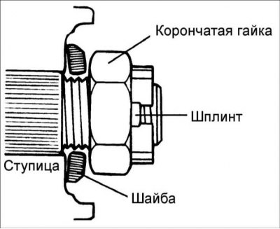
8. Install the cotter pin.
9. Install the wheel.