
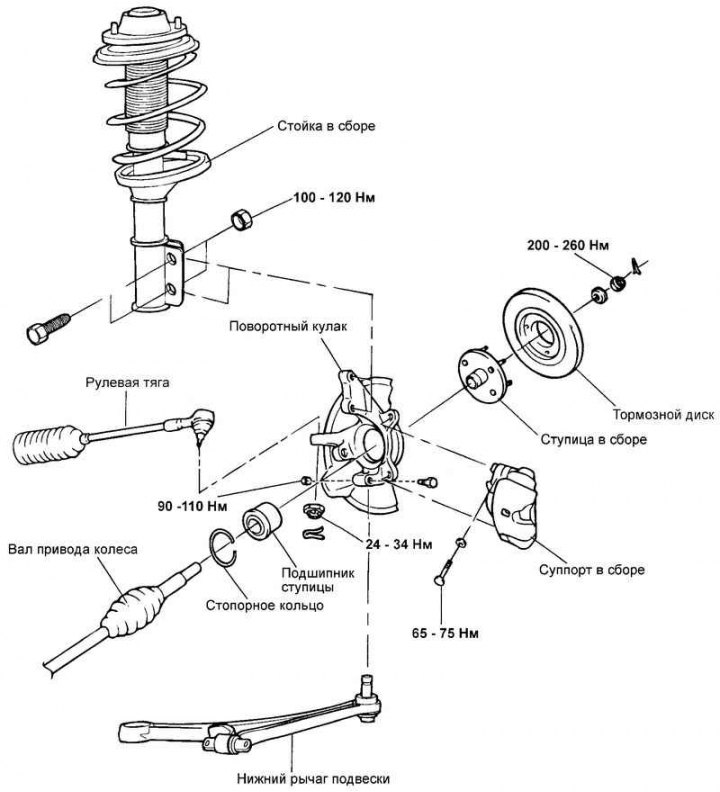
Fig. 3.147. Front wheel hub and steering knuckle
Removal
Remove the front wheel.
Remove the cotter pin and unscrew the nut securing the wheel drive shaft to the front wheel hub.
Remove the disc brake caliper assembly from the steering knuckle and hang it with wire from the front suspension strut.
Remove the wheel speed sensor from the steering knuckle.
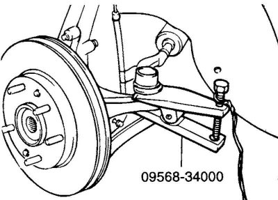
Fig. 3.148. Disconnecting the ball joint
Using a special tool (puller 09568-34000), disconnect the ball joint of the steering rod end from the steering knuckle (Fig. 3.148).
Note: To prevent the puller from slipping off (09568-34000) tie it with rope or wire first.
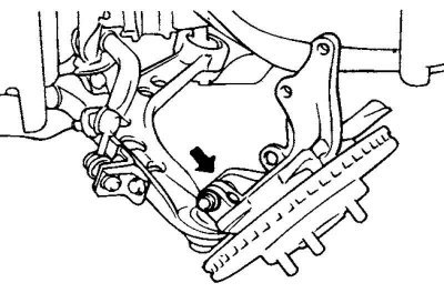
Fig. 3.149. Steering knuckle mounting bolt
Disconnect the steering knuckle mounting bolt from the lower suspension arm ball joint (Fig. 3.149).
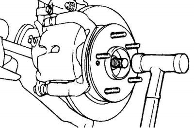
Fig. 3.150. Disconnecting the wheel drive shaft from the wheel hub
Using a plastic hammer, disconnect the wheel drive shaft from the wheel hub (Fig. 3.150).
Remove the front axle assembly.
Disassembly
Remove the two brake disc mounting screws, then remove the brake disc from the wheel hub.
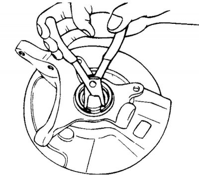
Fig. 3.151. Removing the hub bearing retaining ring
Remove the hub bearing retaining ring (Fig. 3.151).
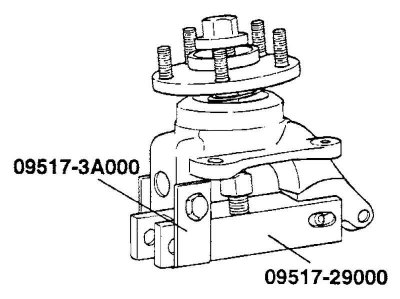
Fig. 3.152. Installing a special tool on the wheel hub
Install the special tool on the wheel hub as shown in Figure 3.152.
Using a special tool, remove the hub from the steering knuckle.
Remove the special tool and protective cover.
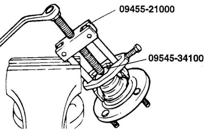
Fig. 3.153. Removing the inner bearing race from the wheel hub
Using a special tool, remove the inner bearing race from the wheel hub (Fig. 3.153).
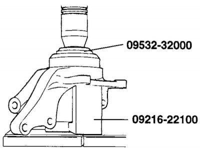
Fig. 3.154. Removing the outer bearing race from the wheel hub
Using the special tool (09495-33100 and 09517-29000), remove the outer bearing race from the steering knuckle (Fig. 3.154).
Examination
Check the hub for cracks and the hub splines for excessive wear.
Check the brake disc for burrs or damage.
Check the steering knuckle for cracks.
Check the bearing for cracks and damage.
Assembly
Apply a thin coat of general purpose grease to the bearing seats in the hub and steering knuckle.
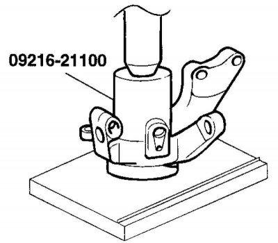
Fig. 3.155. Pressing the bearing into the steering knuckle
Using the special tool (09495-33100 and 09517-29000), press the bearing into the steering knuckle (Fig. 3.155).
Note: To prevent damage to the bearing assembly, the pressing force must be applied to its outer race.
Note: Always install a new bearing assembly (do not install a used bearing).
Install the protective cover.
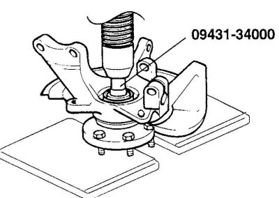
Fig. 3.156. Pressing the hub into the steering knuckle
Using a special tool (09495-33100) press the hub into the steering knuckle (Fig. 3.156).
Note: To prevent damage to the bearing assembly, the pressing force must be applied to the inner race of the bearing.
Install the brake disc.
Rotate the hub several times to ensure the bearing is seated correctly.
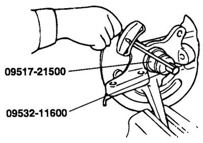
Fig. 3.157. Measuring the moment of the beginning of rotation of the wheel hub bearing
Measure the moment when the wheel hub bearing starts to rotate (Fig. 3.157)
The maximum permissible value of the starting torque of the hub bearing: 1.8 N·m or less.
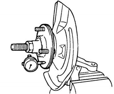
Fig. 3.158. Measuring the axial clearance of the wheel hub bearing
If the bearing rotation start torque is 0 Nm, measure the axial clearance of the wheel hub bearing (Fig. 3.158).
If the axial clearance is greater than the maximum permissible value when the special tool nut is tightened to a torque of 200–260 N·m, the bearing, hub, and steering knuckle are not installed correctly. In this case, disassemble the unit and repeat the assembly procedure.
Hub bearing axial clearance: 0.08 mm or less.
Remove the special tool (09517-21500).