Contents: Removal the retaining rings ⇓ Removal the mounting bolts ⇓ Removal the self-locking…⇓ Removal the intermediate support…⇓ Removal a CV joint with a length…⇓ Removal the protective cover of the…⇓ Examination ⇓ Installing a CV joint with a length…⇓ Installing the protective cover clamp ⇓ Installing the intermediate support…⇓ Installing the CV joint mounting…⇓ Installing the intermediate support…⇓ Installing the universal joint…⇓ Installing retaining rings ⇓
Removal the retaining rings
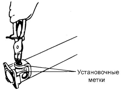
Fig. 3.105. Removing the retaining rings
Before removing the retaining ring, apply installation marks to the relative positions of the crosspieces and forks of the universal joint (Fig. 3.105).
Remove the retaining rings using a special tool.
Removing the universal joint cross bearing
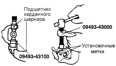
Fig. 3.106. Removing the universal joint crosspiece bearing
Using a special tool, press out the bearing from the crosspiece and the cardan joint fork (Fig. 3.106).
Caution! Do not knock out the bearings when removing them, as this may lead to imbalance of the driveshaft.
Removal the mounting bolts
CV joint with length compensator (DOJ) assembly
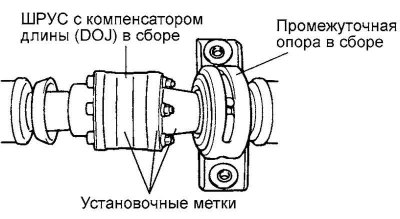
Fig. 3.107. Marks of the relative position of the flange and the CV joint with a length compensator (DOJ) in assembly
Apply marks to the relative positions of the flange and the CV joint with the length compensator (DOJ) assembly (Fig. 3.107).
Loosen the bolts securing the CV joint with the length compensator (DOJ) assembly and disconnect the CV joint from the flange.
Removal the self-locking nut/removing the flange
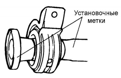
Fig. 3.108. Marks of the relative position of the rear propeller shaft and flange
[The article is based on information website hyundaibook.ru]
Mark the relative positions of the rear propeller shaft and flange (Fig. 3.108).
Remove the flange from the rear propeller shaft.
Removal the intermediate support assembly
Remove the intermediate support assembly.
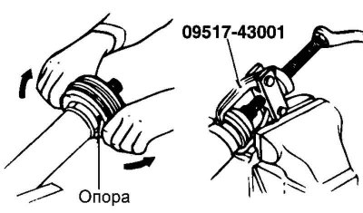
Fig. 3.109. Removing the intermediate support assembly
Pull the intermediate support bracket and install the special tool (Fig. 3.109).
Removal a CV joint with a length compensator (DOJ)
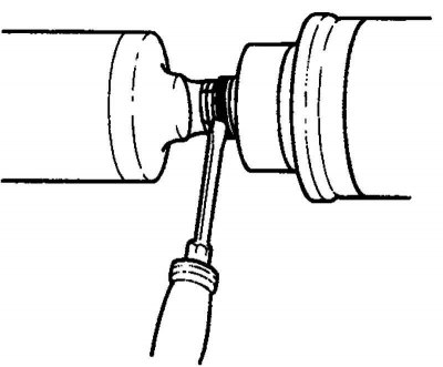
Fig. 3.110. Removing the protective cover
Remove the protective cover from the Lebro CV joint assembly (Fig. 3.110).
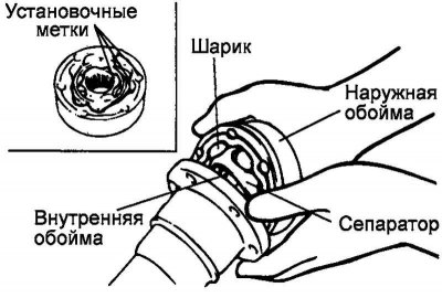
Fig. 3.111. Position of the ball and separator
Apply installation marks for the relative positions of the outer race, separator and inner race of the CV joint using a scriber (Fig. 3.111).
Note: Write down the location of the balls so as not to confuse their original location during installation.
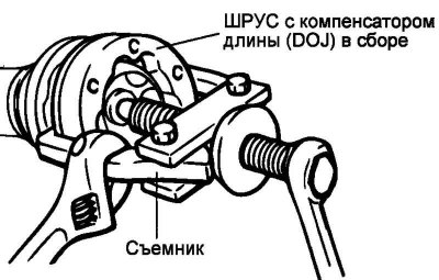
Fig. 3.112. Removing the inner race and CV joint separator from the front propeller shaft
Using a universal (commercially available) puller, remove the inner race and CV joint separator from the front propeller shaft (Fig. 3.112).
Removal the protective cover of the CV joint with a length compensator (DOJ)

Fig. 3.113. Removing the CV joint protective cover
If you plan to reinstall the CV joint protective boot with a length compensator (DOJ), then before removing the CV joint protective boot, wrap the splines of the rear propeller shaft with insulating tape (Fig. 3.113).
Examination
Check the driveshaft splines for wear or damage.
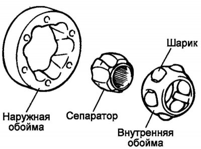
Rice. 3.114. CV joint separator "Lebro"
Check the ball grooves on the outer race and inner race of the Lebro CV joint for uneven wear, damage or rust (Fig. 3.114).
Check the surface of the balls for rust, wear or other damage.
Check the Lebro CV joint separator for rust or damage.
Installing a protective CV joint boot with a length compensator (DOJ)
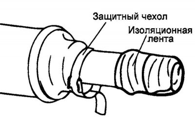
Fig. 3.115. Installing the protective cover
Wrap the driveshaft splines with insulating tape and install the CV joint protective boot with a length compensator (DOJ) (Fig. 3.115).
Installing a CV joint with a length compensator (DOJ)
Apply a thin layer of special consistent grease to the grooves under the balls on the outer and inner CV joint races.
Recommended lubricant: REAMAX FS No.1
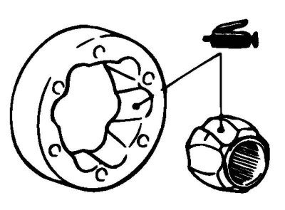
Fig. 3.116. Lubrication application areas
Install the separator on the inner CV joint race, aligning the installation marks, and install the two balls so that they are located in mutually opposite grooves. In this case, both balls should be installed in the same grooves in which they were installed before disassembling the CV joint (Fig. 3.116).
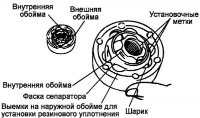
Fig. 3.117. Installing the inner race and separator
Install the inner race and separator assembly into the outer race, aligning the installation marks of their relative positions (Fig. 3.117).
Install the remaining balls into the grooves according to their original location.
Check that the outer CV joint race rotates smoothly on the outer race.
Apply special grease to the CV joint with length compensator (DOJ) assembly.
Recommended lubricant: REAMAX FS NO. 1 (95±5 grams).
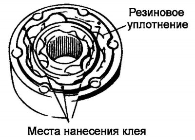
Fig. 3.118. Places of glue application
Apply a small amount of special glue to three points on the surface of the ball grooves located at equal distances from each other around the circumference of the CV joint with a length compensator (DOJ), in which there are grooves for the rubber seal, and then install the rubber seal on the CV joint with a length compensator (DOJ) (Fig. 3.118).
Recommended Adhesive: 3M ATD Part # 8121, 3M ATD Part # 8155, or equivalent
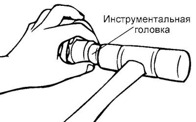
Fig. 3.119. Installing a CV joint using a tool head
Install the CV joint with the length compensator (DOJ) assembly on the driveshaft, aligning the holes for the mounting bolts. Install a suitable tool head on the inner race of the CV joint and, tapping with a hammer with a plastic striker, ensure a tight fit of the CV joint in place (Fig. 3.119).
Note: When installing, position the CV joint with the length compensator (DOJ) so that the side with the grooves on which the rubber CV joint seal was previously installed faces the protective CV joint boot.
Again align the bolt holes on the CV boot and the DOJ assembly with the mounting bolts, and install the boot onto the CV joint.
Install the rubber flange seal on the flange. The installation procedure is completely similar to the procedure described above.
Installing the protective cover clamp
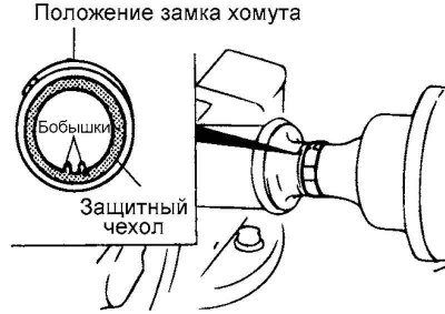
Fig. 3.120. Position of the protective cover clamp lock
Caution! Position the boot clamp lock so that it is on the opposite side of the boot from the boot vent bosses. Make sure there is no grease around the boot vent bosses as grease will impede ventilation through the channels (Fig. 3.120).
Installing the intermediate support assembly/installing the flange/installing the self-locking nut
Install the bearing and retainer into the groove of the intermediate support.
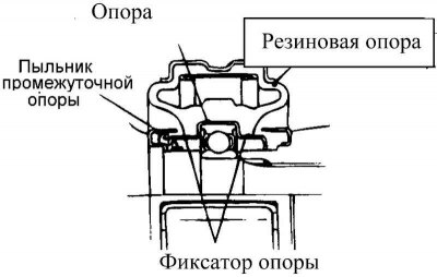
Fig. 3.121. Intermediate support installation diagram
Install the intermediate support assembly onto the front propeller shaft so that the intermediate support boot is located on the front propeller shaft side (Fig. 3.121).
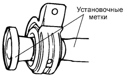
Fig. 3.122. Alignment of marks on the flange and rear propeller shaft
Align the previously made relative position marks on the flange and the rear propeller shaft (Fig. 3.122).
Press the flange and intermediate support assembly firmly together, tightening the self-locking nut.
Installing the CV joint mounting bolts with a length compensator (DOJ) assembly
Align the previously made relative position marks on the flange and the DOJ assembly before installing the mounting bolts.
Connect the flange and the CV joint with the length compensator (DOJ) assembly with the mounting bolts.
Check the flange and the DOJ for grease leaks.
Installing the intermediate support assembly
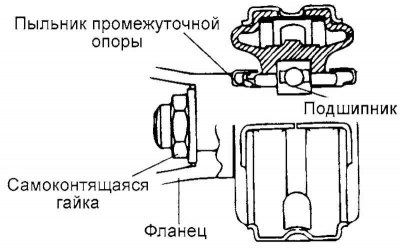
Fig. 3.123. Intermediate support installation diagram
Install the bearing and retainer into the groove of the rubber support of the intermediate support mounting bracket (Fig. 3.123).
Install the intermediate support boot assembly so that it is located at the front side.
Installing the universal joint crosspiece and universal joint crosspiece bearings
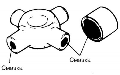
Fig. 3.124. Places of application of consistent lubricant
Apply general purpose grease to the following areas of the universal joint and bearings (Fig. 3.124).
Crosspiece journals and oil collection grooves.
Working edges of oil seals.
Needle bearings.
Recommended lubricant: ALVANIA EP GRADE No.2
Caution! Do not apply excessive amounts of grease. Excessive grease will result in assembly difficulties and incorrect selection of retaining rings.
Using a special tool, press the bearings into the cardan joint forks in accordance with the following sequence of operations.
Mount the appropriate mandrel on the special tool.
Install both bearings into the cardan joint fork and press them in using a special tool.
Installing retaining rings
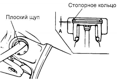
Fig. 3.125. Retaining ring installation diagram
Install snap rings of equal thickness on both sides of the universal joint yoke.
Using a bronze drift, press the bearing and crosspiece into the cardan joint fork on one side.
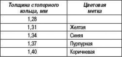
Measure the axial clearance of the universal joint cross bearing (between the retaining ring and the bearing) using a flat feeler gauge. If the axial clearance exceeds the maximum permissible value, adjust it by selecting a retaining ring of suitable thickness.
Nominal value: 0.02–0.06 mm.