
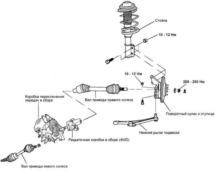
Fig. 3.126. Front wheel drive shaft components
Removal
Raise the vehicle and remove the front wheel.
Remove the cotter pin and unscrew the nut securing the wheel drive shaft to the wheel hub.
Drain the oil from the gearbox.
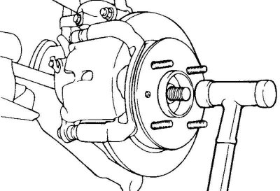
Fig. 3.127. Disconnecting the wheel drive shaft
Using a plastic hammer, disconnect the wheel drive shaft from the wheel hub (Fig. 3.127).
Pull the wheel hub outward from the vehicle and separate the wheel drive shaft from it.
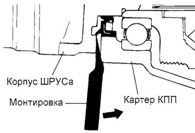
Fig. 3.128. Disconnecting the wheel drive shaft from the gearbox
Insert a pry bar between the gearbox housing and the CV joint housing of the wheel drive shaft, and then disconnect the wheel drive shaft from the gearbox (Fig. 3.128).
Caution! Be careful when disconnecting the wheel drive shaft with a pry bar, do not damage the gearbox housing and the CV joint of the shaft.
Caution! To avoid damaging the seal, do not insert the pry bar too deeply (maximum 7 mm).
Caution! Do not pull out the wheel drive shaft with significant force, as such an operation will damage the internal parts of the Birfield BJ or Tripod TJ CV joint of the wheel drive shaft (rupture of the boot or damage to the bearing).
Caution: Use a special plug to close the hole in the gearbox to prevent dirt and foreign particles from getting inside.
Hold the wheel drive shaft securely.
Always replace the snap ring (retainer ring) after disconnecting the wheel drive shaft from the gearbox.
Examination
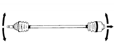
Fig. 3.129. Checking the drive shaft
Check the protective cover of the CV joint of the wheel drive shaft for damage and deterioration of its technical condition.
Check the ball joints for excessive wear and tear and for mobility.
Check the splined portion of the wheel drive shaft (and hub) for excessive wear or damage.
Check the dynamic damper for damage or cracks.
Installation
Lubricate the drive shaft splines and the contact surfaces of the differential housing (in the gearbox) with transmission oil.
Before installing the wheel drive shaft, position the retaining ring so that its lock faces downward.
After installing the wheel drive shaft, check that the shaft is securely fixed and cannot be removed by hand.
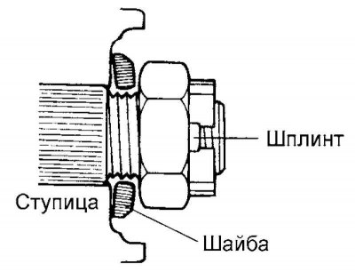
Fig. 3.130. Installing the washer and nut for fastening the drive shaft
Install the washer with the convex side facing outward, then install the wheel drive shaft mounting nut and cotter pin (Fig. 3.130).
Always replace the drive shaft locking nut and cotter pin with new ones each time the shaft is disconnected from the hub.