
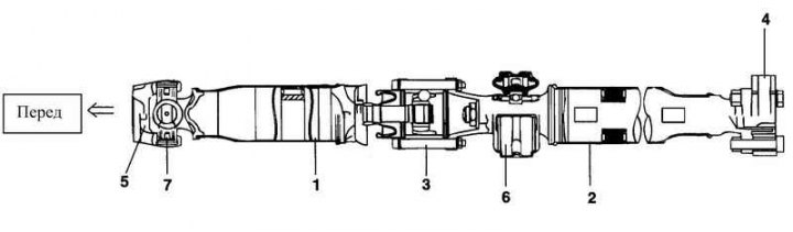
Rice. 3.96. Cardan shaft assembly: 1 – front propeller shaft; 2 – rear propeller shaft; 3 – CV joint with length compensator (DOJ) assembly; 4 – flange fork; 5 – stopper; 6 – intermediate support assembly; 7 – cardan joint assembly
Removal
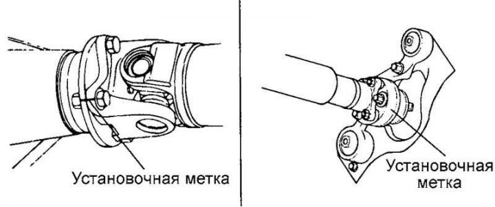
Fig. 3.97. Installation marks
After applying the installation marks to the relative positions of the propeller shaft flange and the differential drive gear flange, remove the propeller shaft (Fig. 3.97).
Note: Remove the propeller shaft in a straight and horizontal direction so as not to damage the protective boot on the edge of the metal part of the boot. Damage to the protective boot can be prevented and the removal operation can be simplified by inserting a piece of cloth or similar material into the narrowing of the protective boot.
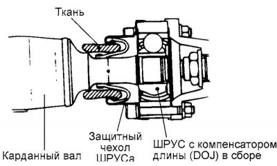
Fig. 3.98. CV joint mounting unit of the propeller shaft
Examination
Check the driveshaft forks for wear, deformation or cracks.
Check the cardan shaft pipe for deflection (beating), deformation and twisting.
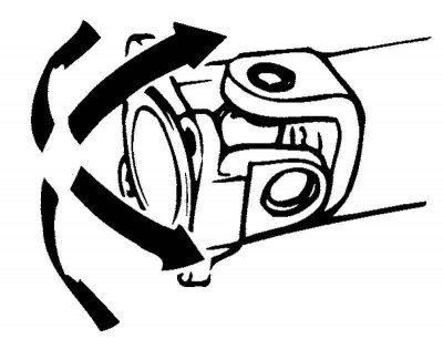
Fig. 3.99. Checking the smooth movement of cardan joints
Check the smooth movement of the cardan joints in all planes (Fig. 3.99).
Check the smooth rotation of the intermediate support bearing of the propeller shaft.
Check the rubber fastening elements of the intermediate support of the cardan shaft for damage and deterioration of technical condition.
Check the flange for damage and deterioration in technical condition.
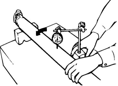
Fig. 3.100. Checking the cardan shaft runout
Check the runout of the cardan shaft using a dial indicator (Fig. 3.100).
Maximum permissible value: 0.5 mm.
Installation
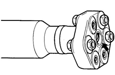
Fig. 3.101. Place of application of samzka
[The original source of the article is the website HYUNDAIBOOK]
Apply grease to the central part of the flange (Fig. 3.101).
Recommended lubricant: ALVANIA EP#2 (8-10 grams).
Lightly insert the center portion of the flange into the differential pinion gear.
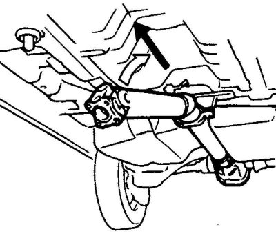
Fig. 3.102. Installing the cardan shaft
Note: Straighten the propeller shaft for assembly. Support the intermediate support assembly (Fig. 3.102).
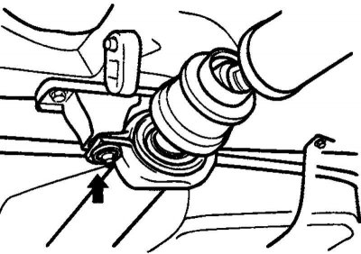
Fig. 3.103. Installing the intermediate support mounting bracket
Temporarily install the intermediate support mounting bracket (Fig. 3.103).
Note: Install the intermediate support mounting bracket so that the "R" alignment mark faces toward the rear of the vehicle.
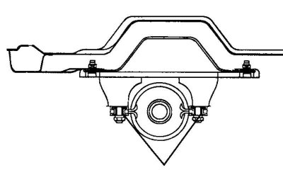
Fig. 3.104. Flange installation diagram
Install the flange so that the marks are facing upwards as shown in Figure 3.104.
Align the relative position marks of the propeller shaft flange and the differential pinion flange. Install the propeller shaft.
Tighten the intermediate support mounting bracket to the specified torque.
Tightening torque: 40–50 Nm.