
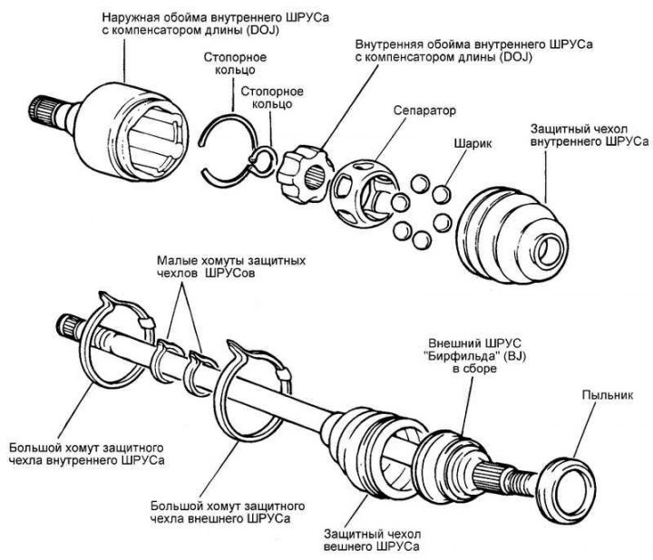
Fig. 3.131. Front wheel drive shaft (CV joint with length compensator (DOJ) and Birfield CV joint (BJ))
Disassembly
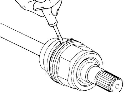
Fig. 3.132. Removing the protective cover mounting clamp
Remove the clamps securing the inner CV joint protective cover and remove the protective cover from the outer race of the inner CV joint (Fig. 3.132).
Attention! Do not disassemble the outer CV joint of the "Birfield BJ".
(The original article is posted on the portal: «HYUNDAIBOOK.ru»)
Attention! A special consistent grease is used to lubricate the CV joints of the wheel drive shaft. Do not mix old and new grease, or different types of consistent grease.
Attention! After removal, replace the CV joint protective boot clamps with new ones.
Caution: Be careful not to damage the protective cover when removing it.
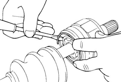
Fig. 3.133. Removing the retaining ring
Using a flat-head screwdriver, remove the large retaining ring from the outer CV joint race (Fig. 3.133).
Pull the wheel drive shaft out of the outer CV joint race.
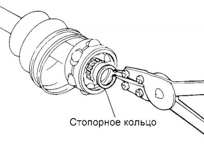
Fig. 3.134. Removing the small retaining ring
Remove the small retaining ring and extract the inner CV joint race complete with separator and balls (Fig. 3.134).
Clean the inner race of the CV joint together with the separator and balls without disassembling the unit.
Remove the outer CV joint protective boot clamps and the protective boot from the outer CV joint housing.
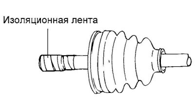
Fig. 3.135. Installing adhesive protective tape
Caution! If you plan to reinstall the CV joint protective boot, wrap the splined part of the shaft with (plastic) insulating tape to avoid damaging the boot (Fig. 3.135).
Examination
Check the inner CV joint outer race, inner race, separator and balls for damage or rust.
Check the splined portion of the wheel drive shaft for signs of increased wear.
Make sure there is no water, foreign particles, dirt or rust in the outer CV joint boot.
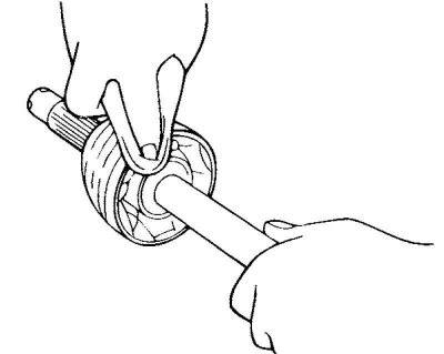
Fig. 3.136. Cleaning the outer CV joint
Caution! If you intend to reinstall the outer CV joint assembly, do not remove the grease from it. Check for foreign particles in the CV joint grease. If necessary, completely clean the outer CV joint assembly from dirt and grease, then apply new consistent grease to the CV joint (Fig. 3.136).
Assembly
Wrap (plastic) insulating tape around the splined portion of the drive shaft on the inner CV joint side to avoid damaging the boot.
Apply grease to the wheel drive shaft and install the CV joint boots.
Recommended lubricant
Outer CV joint (BJ): CENTOPLEX 278M/ 136K.
Inner CV joint (DOJ): AMBLYGON TA 10/2A.
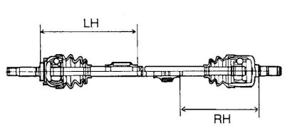
Fig. 3.137. Dynamic damper mounting diagram
To install the dynamic damper, hold the outer CV joint and the wheel drive shaft so that they are in a straight line and secure the dynamic damper with a clamp in the places shown in Figure 3.137.
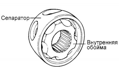
Rice. 3.138. Separator installation
Apply special consistent grease to the inner race and the CV joint separator. Install the separator so that the distance between it and the inner race corresponds to that shown in Figure 3.138.
Note: Use the special grease from the repair kit.
Apply special consistent grease to the inner CV joint separator and install the balls into the separator.
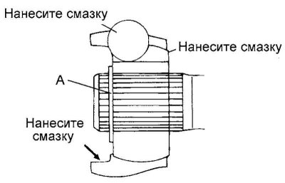
Fig. 3.139. Installing the inner CV joint
Position the (A) side of the inner CV joint as shown in Figure 3.139.
Install the inner CV joint race onto the wheel drive shaft and secure with a retaining ring.
Apply special consistent grease to the outer race of the inner CV joint, install it on the wheel drive shaft and secure it with a retaining ring.
Fill the inner CV joint protective boot with special grease and install it in place.
Secure the inner CV joint protective cover with clamps.
Add special consistent grease to the outer CV joint housing in an amount that corresponds to the amount of grease removed during the inspection.
Install the outer CV joint protective boot.
Secure the outer CV joint protective cover with clamps.
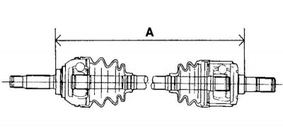
Fig. 3.140. Installing the clamps of the protective covers
Install the clamps of the outer CV joint protective boots at the appropriate distance from each other (to ensure the required volume of air inside the boot) and then tighten the clamps securely (Fig. 3.140).