
Contents: Disassembly ⇓ Assembly ⇓
Disassembly
Remove the clamps securing the protective cover.
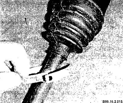
Remove the protective cover from the inner hinge housing.
Remove the inner joint housing from the drive shaft.
Remove old grease from the constant velocity joint.
Remove the snap ring from the end of the drive shaft.
Remove the inner race with balls from the drive shaft.
Using paint, mark the relative positions of the inner ring and separator.
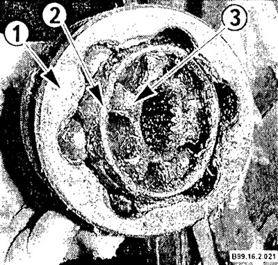
1 - CV joint housing;
2 - separator;
3 - inner ring.
Using a screwdriver blade, remove the balls from the separator.
(The article is based on information website: «HyundaiBook.ru»)
Rotate the inner ring 90°, aligning the inner ring tabs with the separator windows and remove the inner ring from the separator.
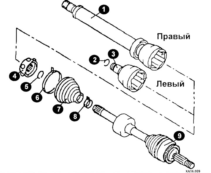
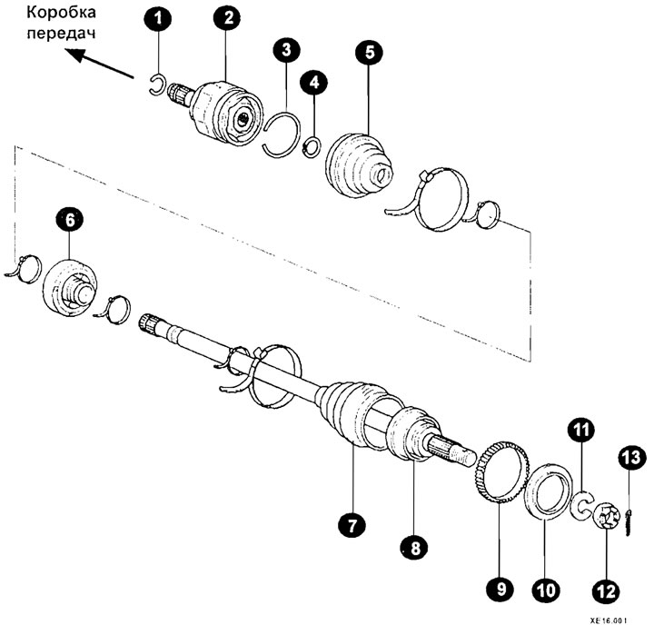
Drive shaft elements (models produced before 2002)
1 - shaft/housing;
2, 5 - retaining ring;
3 - CV joint housing (TJ);
4 - hinge assembly;
6, 8 - clamp;
7 - protective cover;
9 - hinge assembly.
Drive shaft elements (models from 2002)
1 - retaining ring;
2 - hinge (DOJ);
3, 4 - retaining ring;
5 - case;
6 - dynamic damper;
7 - case;
8 - hinge (BJ);
9 - toothed wheel (models with ABS);
10 - oil seal;
11 - washer;
12 - nut;
13 - cotter pin.
Using solvent, clean all hinge parts. Check the condition of the parts for pitting, scratches, cracks and damage. If there are any defects, replace the joint assembly.
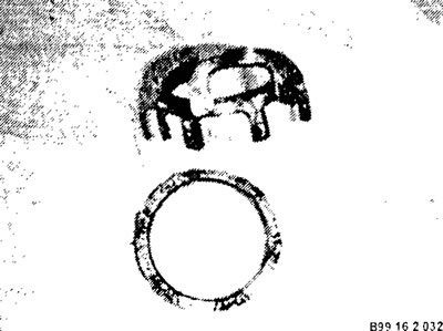
The photo shows a broken hinge separator
Assembly
Install the inner ring into the separator, aligning the alignment marks.
Insert the balls into the separator windows.
To avoid damaging the protective cover when installing it on the drive shaft, wrap the splines of the drive shaft with adhesive tape.
Slide the small boot retaining clip onto the drive shaft, then slide the boot onto the drive shaft and remove the adhesive tape.
Further assembly is carried out in reverse order.
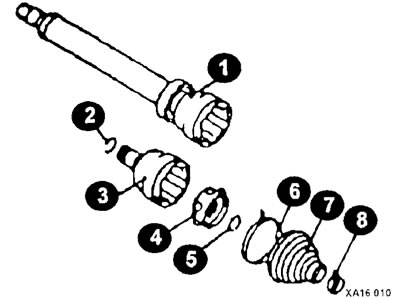
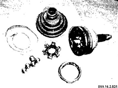
CV joint repair kit
1 - right wheel CV joint housing;
2 - retaining ring;
3 - left wheel CV joint housing;
4 - hinge assembly;
5 - retaining ring;
6, 8 - clamp;
7 - case.