


Contents: Removal ⇓ Installation ⇓
Removal
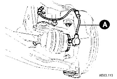
Remove the brake hose clamp, the wheel speed sensor (A) wire connector (cars with ABS) and anti-roll bar.
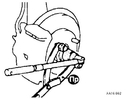
Using the hub release guard, unscrew the wheel drive shaft mounting nut.
Loosen the nut securing the lower arm ball joint pin to the front suspension strut.
Using a puller, remove the ball joint pin from the steering knuckle.
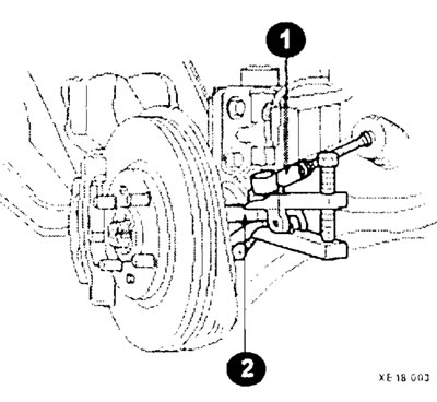
Loosen the nut securing the ball joint pin of the tie rod end (1) to the front suspension strut (2). Using a puller, remove the ball joint pin from the steering knuckle.
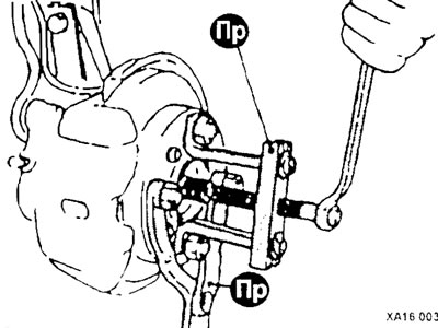
Using the tool, push the drive shaft end out of the hub.
Models with manual transmission: After unscrewing the bolt and removing the split pin, remove the wheel drive shaft from the gearbox.
Models with automatic transmission: insert the crowbar (3) between the gearbox housing (4) and the wheel drive shaft (2) (cV joint housing), as shown in the figure and push the shaft out of the gearbox. Be careful not to damage the seal.
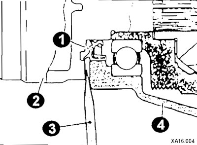
It is prohibited to pull out the drive shaft without a mount; such an operation will lead to damage to the CV joint (type TJ)
If you need to move the car to another location (the bearing must be loaded with the weight of the vehicle), then temporarily tighten the nut with the device as shown in the figure.
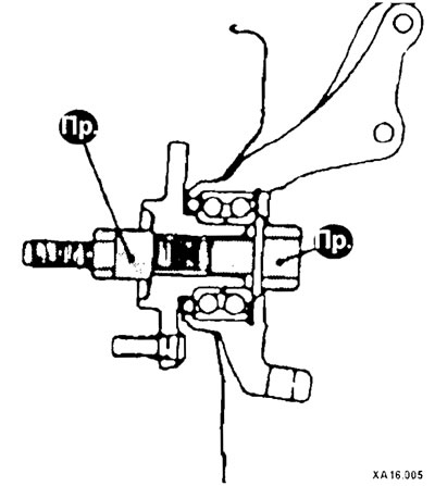
After knocking out the split pin, remove the right wheel drive shaft from the gearbox (cars with manual transmission).
Remove the wheel drive shaft from the gearbox (cars with automatic transmission).
Remove the split retaining ring from the shaft (cars with automatic transmission).
Caution: On vehicles with ABS, when removing and installing the wheel drive shaft, special care must be taken not to damage the wheel speed sensor rotors mounted on the outer CV joint housings (type BJ).
Installation
Installation is carried out in reverse order, taking into account the following:
Install the wheel drive shaft into the hub and into the gearbox. When installing the drive shaft into the transmission, apply grease to the shaft splines on the transmission side and ensure that the pin hole on the end of the drive shaft aligns with the pin hole on the transmission shaft. If these holes do not align, rotate the wheel drive shaft 180° and reconnect the wheel drive shaft to the gearbox shaft.
Note: Due to the odd number of splines on the drive shaft, when the drive shaft is rotated 180°, the split pin hole will be offset by half the pin hole diameter.
Apply sealant to the split pin and then insert it into the hole in the wheel drive shaft. After installing the pin, apply sealant to both sides of the pin holes to completely seal them.
The washer under the drive shaft mounting nut must be installed with the convex side facing the nut.
Tighten the drive shaft mounting nut using a torque wrench.
Install the brake hose retainer, wheel speed sensor wire connector (cars with ABS) and anti-roll bar.
Connect the speedometer drive cable, stabilizer bar and side lower cover.