
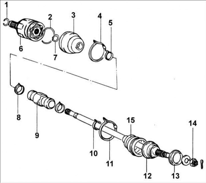
1 - retaining ring; 2 - retaining ring; 3 - protective cover; 4 - clamp; 5 - collar; 6 - SHRUS of ball type; 7 - retaining spring ring; 8 – dynamic damper clamp; 9 - dynamic damper; 10 - clamp; 11 - clamp; 12 - SHRUS Birfield; 13 - dustproof ring; 14 - nut, 220–260 Nm; 15 - protective cover.
Disassembly
Warning! Do not disassemble the Birfield type CV joint.
Warning! To lubricate the CV joints, use only special grease.
Warning! When assembling the CV joint, it is necessary to install new clamps.
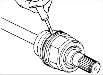
1. Remove the clamps and pull off the protective cover from the ball joint of the drive shaft.
Warning! Be careful not to damage the protective cover.
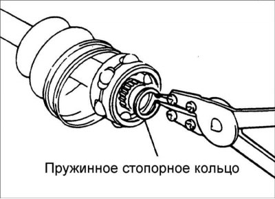
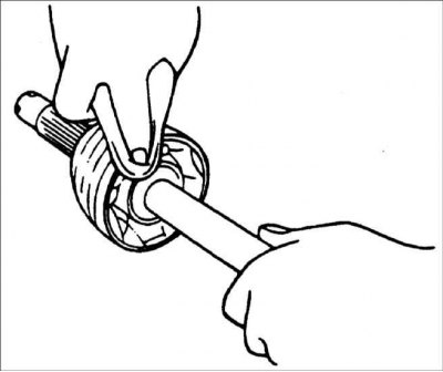
2. Remove the retaining ring with a flat blade screwdriver.
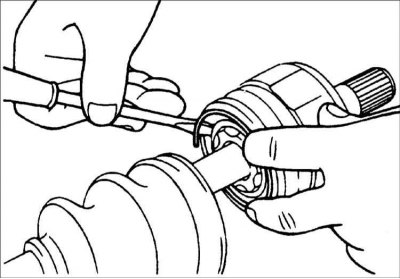
3. Remove the ball joint from the drive shaft.
4. Remove the circlip, take out the inner ring, housing and balls as an assembly.
5. Without disassembly, clean the inner ring, body and balls.
6. Remove the clamps and pull off the protective covers of the ball CV joint and the Birfield CV joint.
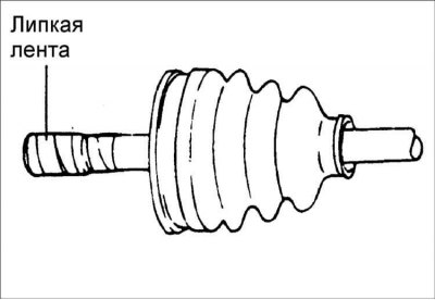
Warning! If the boot is to be reused before removing the boot to protect it, wrap the driveshaft splines with tape.
Examination
1. Check the ball joint for signs of rust, damage to the outer ring, inner ring and balls.
2. Check the condition of the drive shaft splines.
3. Check for signs of rust, water and foreign objects in the protective boot of the Birfield CV joint.
Warning! In the Birfield CV joint, you can only change the lubricant.
Assembly
1. Before installing the boot to protect it, wrap the splines of the drive shaft on the side of the ball joint with adhesive tape.
2. Apply grease to the drive shaft and install the boot.
- CV Joint Grease Birfield: MS511–50
- Ball Joint Lubrication: MS511–50
3. To install the dynamic damper, position the Birfield CV joint in a straight line with the shaft, position the damper at a distance of 301±2 mm and secure it with a clamp.
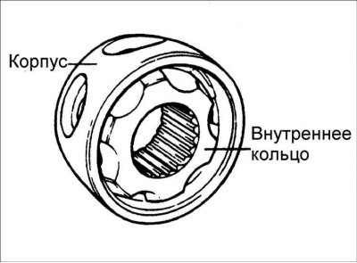
4. Apply grease to inner ring and housing. Install the housing so that the offset on the rolling surface is as shown in the figure.
Warning! Use the grease supplied with the repair kit.
5. Apply grease to the body and balls located in the body.
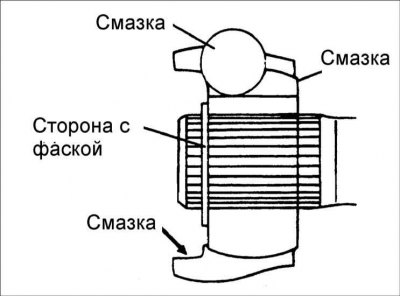
6. Install the hinge as shown in the figure and secure it with a circlip.
7. Put 45±5 g of grease into the outer ring and install it on the drive shaft.
8. Put 30±10 g of grease into the protective cover and place the cover on the hinge.
Protective cover for ball joint
- Total amount of grease: 75±15 g
- Hinge: 45±3g
- Protective case: 30±10 g).
9. Secure the protective cover with clamps.
10. Add as much grease to the Birfield CV joint as was wiped off during the joint inspection.
11. Install covers.
12. Secure the protective cover of the Birfield CV joint with clamps.
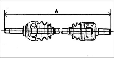
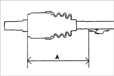
13. Fasten the boots so that the length of the drive shaft matches the required values.
Left drive shaft length:
- With manual transmission: 626.2±2 mm
- With automatic transmission: 644.9±2 mm
Right drive shaft length:
- With manual transmission: 933.2±2 mm
- With automatic transmission: 933.9±2mm