
HyundaiBook.ru
Repair Chevrolet Repair Honda Repair Toyota Repair Land Rover Repair VAZ Repair Renault Repair Nissan
English Русский
Български
Беларускі
Український
Српски
Hrvatski
Română
Polski
Slovenský
Magyar
ArticlesSitemapContacts  


  Accent   Elantra   Getz   Grandeur   Sonata   Santa Fe   Tucson   Others
Accent 1 (1994-1999) Accent 2 (1999-2005) Accent 3 (2005-2010)
  • Main
  • Accent
  • X3 (1994-1999)
  • Power unit
  • Fuel supply (carburetor)
  • Disassembling the carburetor

Disassembling the carburetor (Hyundai Accent X3)

0
Warning: Do not remove the check valve or throttle bodies.


1. Remove the water hose from the throttle body nipple and the wax element nipple (for automatic valve).

2. Remove the mixing chamber rod from the free lever.
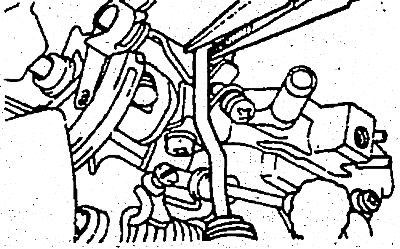
2. Remove the mixing chamber rod from the free lever.


3. Remove the bracket with the connector.
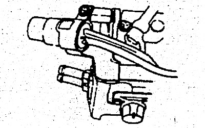
3. Remove the bracket with the connector.


4. Remove the mixing chamber (throttle actuator).
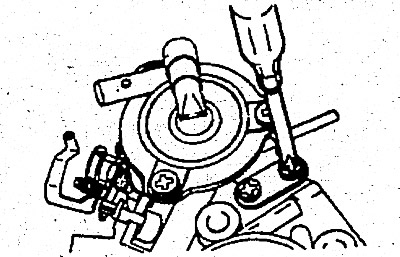
4. Remove the mixing chamber (throttle actuator).


5. Remove the accelerator pump rod from the throttle lever.
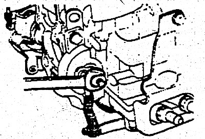


5. Remove the accelerator pump rod from the throttle lever.


6. Unscrew screw "B" of the float chamber cover and remove the throttle body.

7. Unscrew screws "A" and remove the float chamber cover from the main body.
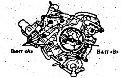
7. Unscrew screws «A» and remove the float chamber cover from the main body.


8. To remove the float chamber cover assembly, insert a screwdriver blade between the enrichment and float chamber covers as shown in the figure, press it lightly and lift it up smoothly.

Warning: Do not use excessive force.
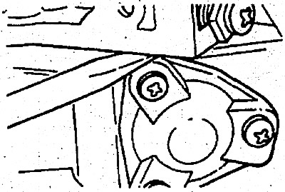

Warning: Do not use excessive force.


9. Remove the pin and pull out the float and needle valve.


Warnings:
1) Do not drop the float or apply excessive load to it.
2) Take care not to damage the end of the needle valve.
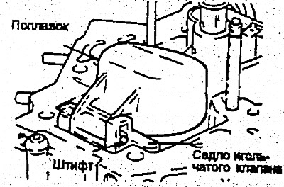

2) Take care not to damage the end of the needle valve.


10. To remove the needle valve seat, use a flat-blade screwdriver to push it out from both sides.

Caution: Take care not to damage the float chamber cover when pressing out the needle valve seat.
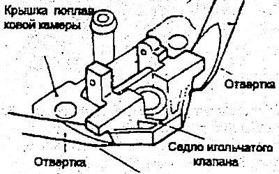

Caution: Take care not to damage the float chamber cover when pressing out the…


11. Remove the holder and pull out the shut-off solenoid valve.
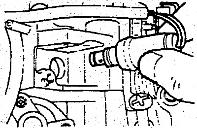
11. Remove the holder and pull out the shut-off solenoid valve.


12. Using a screwdriver or other thin, flat-tipped tool, press down on the retaining section and remove the two terminals from the connector.
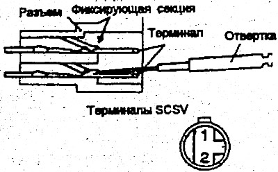


12. Using a screwdriver or other thin, flat-tipped tool, press down on the…


13. Remove the accelerator cable support bracket.
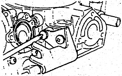
13. Remove the accelerator cable support bracket.


14. Remove the auxiliary jets and the main air jet.

Note: When removing the jets, use a screwdriver that fits the slots exactly and work carefully to avoid damaging the jets.


Note: When removing the jets, use a screwdriver that fits the slots exactly and…


15. Remove the accelerator pump check valve ball and weight.

Note: Turn the camera over; to remove the accelerator pump check valve ball and weight located on the gasket surface.
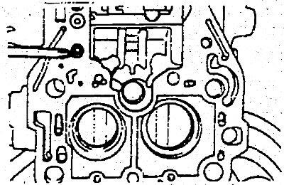


Note: Turn the camera over; to remove the accelerator pump check valve ball and…


16. Separate the float chamber from the throttle body.

17. Remove the main jets.

Note: When removing the main jets, use a screwdriver that fits their slots precisely and work carefully to avoid damaging the jets.


Note: When removing the main jets, use a screwdriver that fits their slots…


18. Remove the three screws securing the enrichment valve cover to the enrichment valve seat on the float chamber. Remove the cover, spring and diaphragm. Unscrew the enrichment valve from the seat.
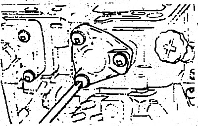
18. Remove the three screws securing the enrichment valve cover to the…


19. Use a screwdriver to loosen the enrichment jet and remove the spring and ball from the enrichment jet valve.


Warning: The valve contains many small parts. Do not lose them.
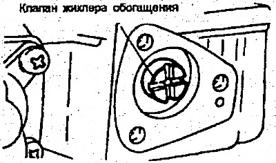

Warning: The valve contains many small parts. Do not lose them.


20. Remove the four screws (thread seal included) securing the accelerator pump cover to the float chamber. Remove the accelerator pump cover, diaphragm, spring, pump body and gaskets.

Note: When reinstalling, apply sealant to the screw threads and ensure that the pump body, gasket and cover are properly seated.


21. Remove the E-clip and outer washer on the second throttle shaft and remove the diaphragm spring from the shaft.

22. Remove the two screws securing the diaphragm bracket to the throttle body and remove the second throttle diaphragm.

23. Remove the auxiliary accelerator pump.

24. To remove the blunt pins, clamp the carburetor in a vice and drill a 2mm diameter hole in the casting surrounding the mixture adjustment screw (MAS), then ream this hole to a diameter of 3mm. Insert a blunt punch into the hole and knock the plug out.
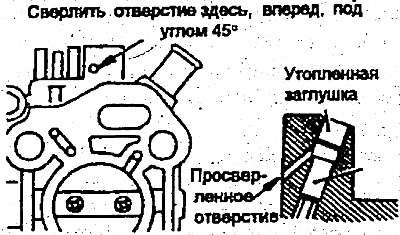
24. To remove the blunt pins, clamp the carburetor in a vice and drill a 2mm…
This article is available at russian, bulgarian, belarusian, ukrainian, serbian, croatian, romanian, polish, slovak, hungarian
This article has been reviewed by: Konstantin Smirnov
Add to social network:

Previous
Accent 1: Fuel supply (carburetor)
Next

Removal the carburetor
The structure and components of the carburetor
Replacing the fuel filter
Fuel tank — removal, inspection and installation
Adjusting the free play of the accelerator cable
Assembling the carburetor
Checking the carburetor
Installing a carburetor
Engine control — removal, inspection and installation
We recommend other articles on the topic of Hyundai manuals:

Disassembling the drive shaft (models with manual transmission). Hyundai Sonata 4 (2001-2012, petrol)
Disassembling the connecting rod and piston group Hyundai Santa Fe 2 (2007-2012, petrol)
Disassembling the clutch Hyundai Tucson 1 (2005-2010)

Link in different formats to this article

Visitor comments
No comments yet


How much will 15 + 44 ?


Accent 3 (2005-2010) 
  • General information
  • User manual
  • Maintenance
  • Power unit
  • Engine repair
  • Cooling and lubrication system
  • Power and exhaust system
  • Engine electrical equipment
  • Engine management
  • Transmission
  • Clutch
  • Mechanical gearbox
  • Automatic gearbox
  • Chassis
  • Front suspension
  • Rear suspension
  • Wheels and tires
  • Steering
  • Brake system
  • Body
  • Exterior (external elements)
  • Interior (internal elements)
  • Heating and ventilation
  • Electrical equipment
  • Equipment and devices
  • Electrical circuits
Accent 2 (1999-2005) 
  • User manual
  • Control devices
  • Starting engine and driving
  • Troubleshooting
  • Power unit
  • SOHC engines
  • DOHC engines
  • Lubrication system
  • Cooling system
  • Decreased toxicity
  • Fuel system
  • Ignition system
  • Transmission
  • Clutch
  • Mechanical gearbox
  • Automatic gearbox
  • Axles and drive shafts
  • Chassis
  • Car suspension
  • Steering
  • Brake system
  • Body
  • Exterior (external elements)
  • Interior (internal elements)
  • Air conditioning system
  • Electrical equipment
  • Equipment and devices
  • Power devices
Accent 1 (1994-1999) 
  • General information
  • Maintenance
  • Power unit
  • SOHC engines
  • DOHC engines
  • Cooling system
  • Intake and exhaust systems
  • Fuel supply (1.3 l, injection)
  • Fuel supply (1.5 l, injection)
  • Fuel supply (carburetor)
  • Transmission
  • Clutch
  • Manual gearbox
  • Automatic gearbox
  • Drive shafts
  • Chassis
  • Car suspension
  • Steering
  • Brake system
  • Body
  • Body elements
  • Electrical equipment
  • Equipment and devices
  • Electrical circuits
HyundaiBook.ru © 2018-2026 · Mobile version · Sitemap: EN BG BY UA RS HR RO PL SK HU · Administration · Site search · Hyundai owners Accent 1 · Accent 2 · Accent 3 · Elantra 1 · Elantra 2 · Elantra 3 · Getz · Sonata 3 · Sonata 4 · Santa Fe 2 · Tucson 1 · Tucson 2 · Matrix ·
This site uses cookies to optimize its functionality. By continuing, you agree to our terms.