
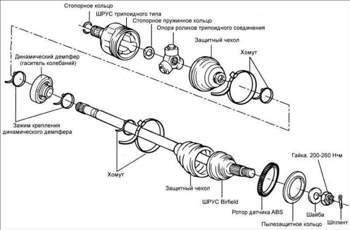
Disassembly
- Do not disassemble the roller support assembly.
- To lubricate CV joints, use only special grease.
- When assembling the CV joint, it is necessary to install new clamps.
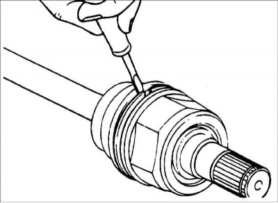
1. Remove the clamps and pull the protective boot off the ball joint (TJ) of the drive shaft.
Caution: Be careful not to damage the protective cover.
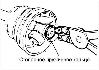
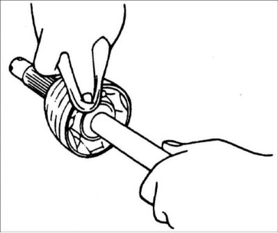
2. Using special pliers, remove the retaining ring and use a hammer through a brass rod to knock the tripod joint roller support off the drive shaft.
3. Clean the tripod roller support.
4. Remove the clamps and pull off the protective boots of the ball CV joint (BJ) and Birfield CV joint (BJ).
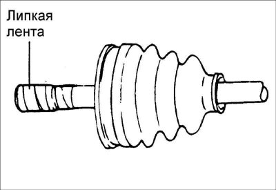
Caution: If the protective boot is to be reused, wrap the drive shaft splines with adhesive tape before removing the boot to protect it.
Examination
1. Check the condition of the drive shaft splines.
2. Check the Birfield (BJ) CV joint protective boot for any traces of rust, water or foreign objects.
3. Check the tripod roller bearing for wear or corrosion.
4. Check the groove inside the CV joint (TJ) for wear or corrosion.
5. Check the dynamic damper for damage.
Assembly
1. Before installing the boot, wrap the splines of the drive shaft on the tripot joint (TJ) side with adhesive tape to protect it.
2. Apply grease to the drive shaft and install the boot.
- Cars with 1.6 and 1.8 l engines with manual transmission: 467.5 (2/0) mm
- Cars with 2.0 l petrol engines with automatic transmission and diesel engines with manual transmission: 469 (2/0) mm
3. To install the dynamic damper, position the Birfield (BJ) CV joint straight in relation to the shaft, install the damper and secure it with a small clamp.
4. Apply grease to the tripod CV joint (TJ) boot and install the boot onto the joint.
5. Install the tripod type CV joint boot mounting clamps.
6. Add as much Birfield grease to the CV joint as was wiped off during the joint inspection.
7. Install the covers.
8. Secure the Birfield CV joint protective cover with clamps.
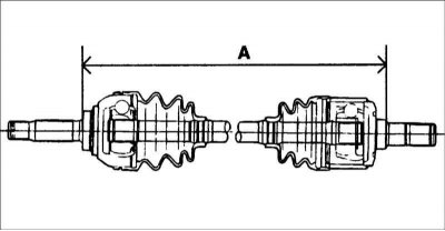
9. Fasten the covers so that the length of the drive shaft corresponds to the required values.
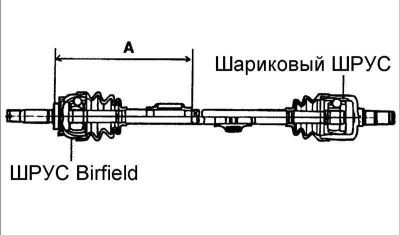
To control the air pressure in the tripod joint boot, maintain the required distance between the boot mounting clamps or the drive shaft length when tightening the clamps. The nominal length of the drive shafts is given in the table.
Nominal length of drive shafts with Birfield (BJ) and tripod type (TJ) CV joints
Name | Left side | Right side |
| Cars with 1.6 and 1.8 l engines with manual transmission | 513.2 (27.5/ –21.6) mm | 789.2 (27.5/ –21.6) mm |
| Cars with 2.0L engines with automatic transmission | 514.2 (27.5/ –21.6) mm | 799.2 (27.5/ –21.6) mm |
| Cars with 2.0L diesel engines with manual transmission | 515 mm | 799 mm |