


Contents: Adjusting the gear clearance ⇓ Checking the starter traction relay ⇓ Checking the holding winding of the…⇓ Checking the return of the traction…⇓ Operational tests (idling) ⇓
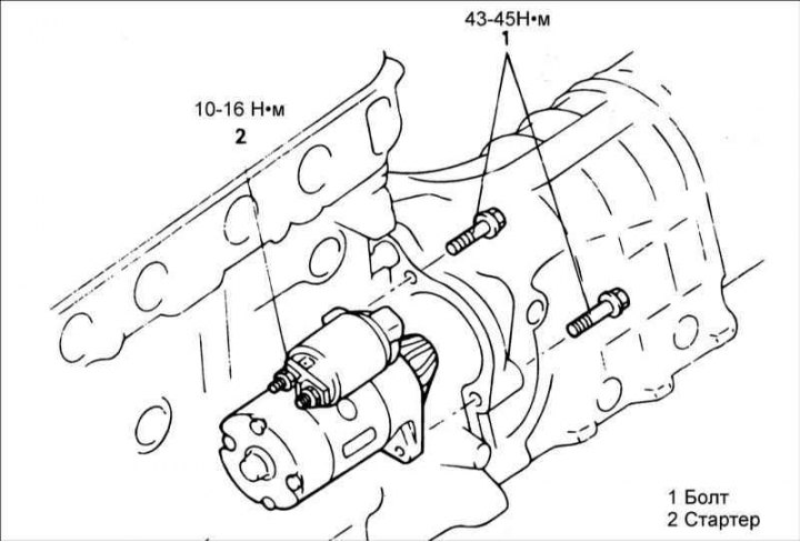
Starter disassembly sequence
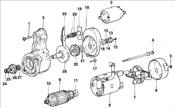
1 – screw; 2 – traction relay solenoid; 3 – front cover; 4 – tension screw; 5 – screw; 6 – back cover; 7 – brush holder; 8 – stator; 9 – rotor; 10 – front bearing; 11 – rear bearing; 12 – screw; 13 – lid; 14 – spring retaining ring; 15 – washer; 16 – plate; 17 – screw; 18 – middle holder; 19 – spring support; 20 – spring; 21 – adjusting washers; 22 – toothed wheel; 23 – lever; 24 – spring retaining ring; 25 – pressure ring; 26 – small gear; 27 – spring; 28 – small gear shaft
Attention! The starter assembly is carried out in the reverse order of disassembly.
Adjusting the gear clearance
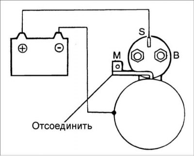
1. Disconnect the starter motor wire from the "M" terminal.
[The material was obtained from a web resource: hyundaibook.ru]
2. Using additional wires, connect the battery terminals to terminals S and M.
Warning! The following check must be performed within 10 seconds, otherwise the traction relay coil may burn out.
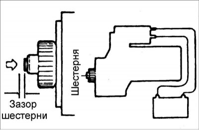
3. Turn on the ignition, the starter gear will move forward. Use your finger to push the gear back and use a feeler gauge to check the clearance between the gear and the stopper.
4. If the gap is different from the required one, adjust it by adding or removing shims between the traction relay and the front cover. Gear clearance: 0.5–0.2 mm.
Checking the starter traction relay
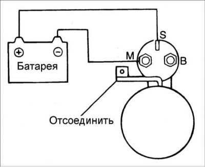
Disconnect the starter motor wire from the "M" terminal. The solenoid is OK if the plunger retracts when the battery terminals are connected to the "S" and "M" terminals. If the pinion does not extend, replace the solenoid.
Warning! This test must be performed within 10 seconds, otherwise the traction relay coil may burn out.
Checking the holding winding of the traction relay
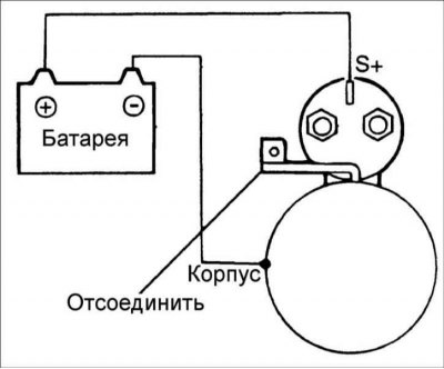
Disconnect the starter motor wire from the "M" terminal. Connect the battery terminals to the "S" terminal and the traction relay housing with additional wires and pull the gear out manually until it stops. If the gear remains in this position, then the holding winding of the traction relay is in good condition.
Warning! This test must be performed within 10 seconds, otherwise the traction relay coil may burn out.
Checking the return of the traction relay plunger
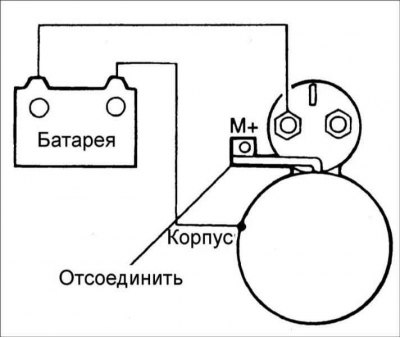
Disconnect the starter motor wire from the "M" terminal. Use additional wires to connect the battery terminals to the "M" terminal and the traction relay housing, while the starter pinion should move forward. Once the wires are disconnected, the starter gear should quickly return to its original position.
Warning! This test must be performed within 10 seconds, otherwise the traction relay coil may burn out.
Operational tests (idling)
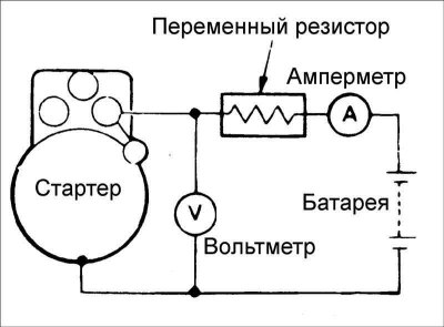
1. To perform the idle test, assemble the circuit shown in the figure.
2. Set the rheostat slider to a position where the voltmeter shows a voltage of 11.5 V, while checking the current consumed by the starter and making sure that the starter shaft turns easily and smoothly. If the consumed current differs from the required one, use the table to determine and eliminate the cause of the malfunction.
Sign | Possible cause |
| High current consumption with low starter shaft speed | Contaminated bearing |
| Friction of the rotor winding on the pole | |
| The rotor winding and field coils are closed to "ground" | |
| The rotor winding is damaged | |
| High current consumption when the starter shaft is not rotating | Solenoid switch shorted to ground |
| The rotor winding and field coils are closed to "ground" | |
| The bearing is seized | |
| There is no current consumption and the starter shaft does not rotate | Damage to the rotor and excitation coil |
| The brush is broken or the flexible brush conductor is torn off | |
| The contact between the brush and the commutator is broken | |
| Low current consumption with low starter shaft speed | Incorrect connection of the excitation coil winding |
| High current consumption at high starter shaft speed | Short circuit in excitation coil |