
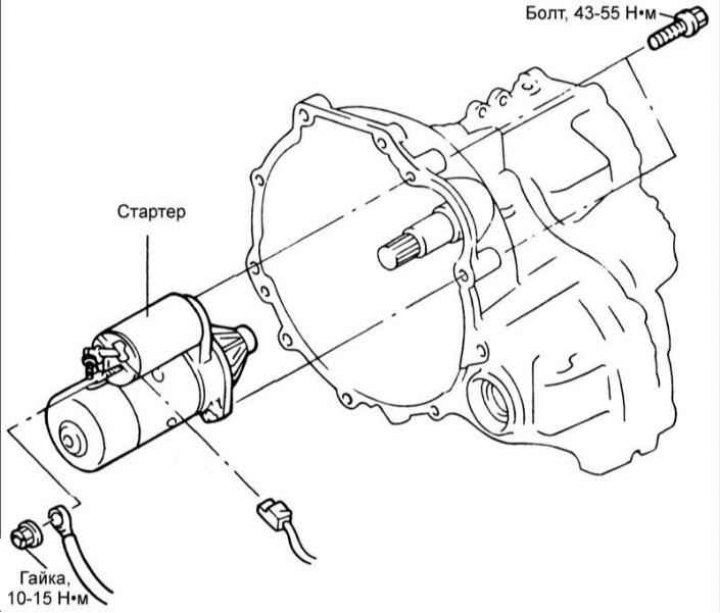
Removal and installation
1. Disconnect a wire from the negative plug of the storage battery.
2. Disconnect a cable of a drive of a speedometer and a gear change.
3. Disconnect from a starter a socket and a wire from the plug.
4. Turn out bolts and remove a starter.
5. Installation is carried out in the reverse order of removal.
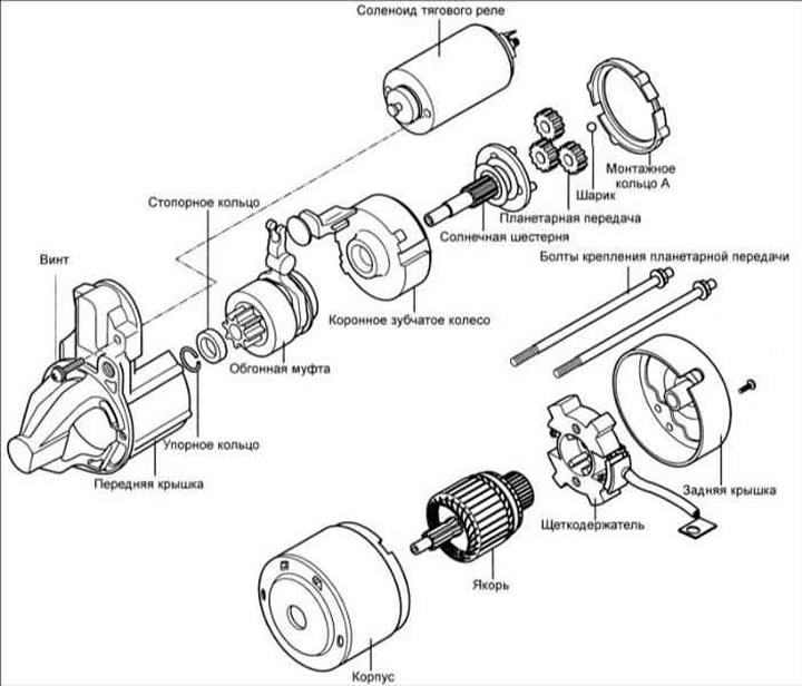
Checking and replacing stator elements
Gear clearance adjustment
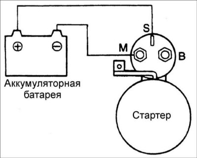
1. Disconnect the starter motor wire from the terminal «M».
2. Use additional wires to connect the battery terminals to the terminals «S» And «M».
3. Turn on the ignition, the starter gear will move forward.
Warning! This check must be carried out within 10 seconds, otherwise the solenoid of the traction relay may burn out.
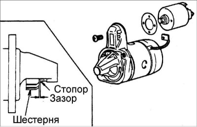
4. Check up a backlash between a gear wheel and a stopper by feeler gauge. If the gap differs from the required one, adjust it by adding or removing spacers between the traction relay and the front cover. Gear clearance: 0.5–0.2 mm.
Check of the traction relay of a starter
1. Disconnect the starter motor wire from the terminal «M».
2. Use additional wires to connect the battery terminals to the terminals «S» And «M».
3. Turn on the ignition, the starter gear will move forward. If the gear does not extend, replace the traction relay.
Warning! This check must be carried out within 10 seconds, otherwise the traction relay coil may burn out.
Checking the holding winding of the traction relay
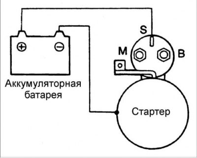
1. Disconnect the starter motor wire from the terminal «M».
2. Use additional wires to connect the battery terminals to the terminal «S» and traction relay housing.
Warning! This check must be carried out within 10 seconds, otherwise the traction relay coil may burn out.
3. If the gear remains in place, then the holding winding of the traction relay is damaged and the traction relay must be replaced.
Checking the return of the traction relay plunger
1. Disconnect the starter motor wire from the terminal «M».
2. Connect the battery terminals with the M terminal and the traction relay housing with additional wires.
Warning! This check must be carried out within 10 seconds, otherwise the traction relay coil may burn out.
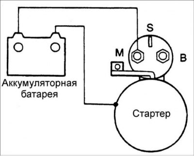
3. Starter gear should move forward. After disconnecting the wires, the starter gear should quickly return to its original position.
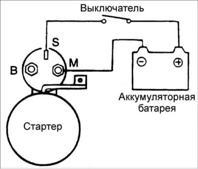
Performance tests (idling)
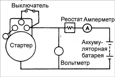
1. To carry out the idle test, assemble the circuit shown in the figure.
2. Set the rheostat motor to a position where the voltmeter will show 11.5 V while checking the current drawn by the starter and make sure the starter shaft turns easily and smoothly. Current: no more than 60 A.
Overrunning gear
To remove the freewheel from the rotor shaft, you must first remove the thrust ring.
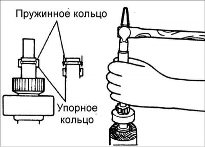
Move the thrust ring to the gear and remove the snap ring. The thrust ring can now be removed from the shaft.
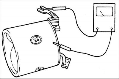
Checking the rotor winding
1. Using an ohmmeter, check the conductivity between the collector and the rotor. If there is continuity, replace the rotor.
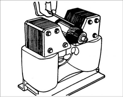
2. In a special device, check the rotor winding. If there are short circuits, replace the rotor. If the steel strip attached to the rotor vibrates, then there are short circuits in the rotor windings.
3. Check up conductivity between collector segments with an ohmmeter. If there is no continuity, replace the rotor.
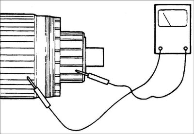
Checking the stator coils
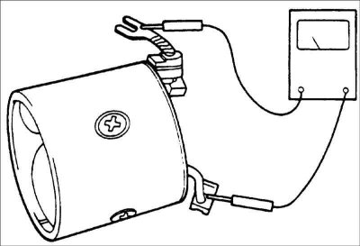
1. Check the conductivity of the stator coils with an ohmmeter. If there is no continuity, replace the stator coils.
2. With the coil in the housing, check for continuity between the coil lead and the starter housing. If there is continuity, replace the stator coils.
Checking the brushes
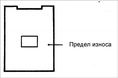
If the brush is worn to the indicated limit, replace it.
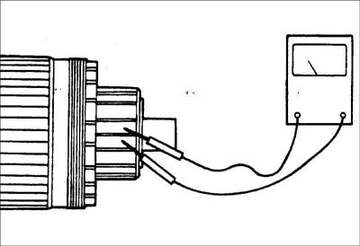
Checking the brush holder
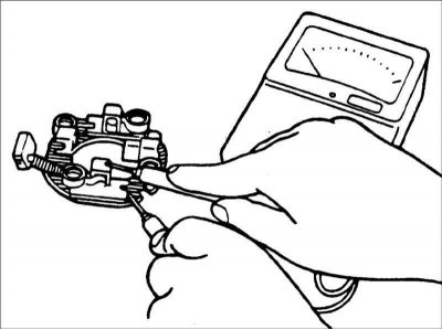
Using an ohmmeter, check the continuity between each insulated brush and plate. If there is continuity, replace the brush holder.
Overrunning clutch test
1. Check the condition of the freewheel gear teeth and replace if damaged. Also check the condition of the flywheel gear teeth.
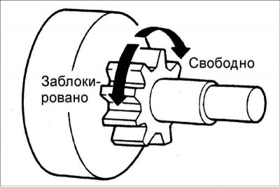
2. Rotate the gear. The gear should turn freely clockwise and lock when turned counterclockwise
Brush replacement
1. Remove the worn brush, being careful not to damage the braided wire.
2. Sand the end of the braided rein with sandpaper to ensure it makes good contact with the new brush.
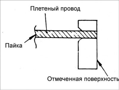
3. Solder the braided wire.
Rear hub replacement
1. Before removing the sleeve, it is necessary to measure the depth of its installation.
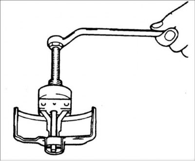
2. The bushing can be removed with a puller as shown in the figure.
3. Install the new bushing to the previously measured depth.
Starter Assembly
1. Install a freewheel onto the front end of the rotor shaft.
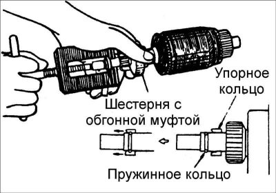
2. Install thrust ring and circlip from the front of the rotor shaft, then move the thrust ring all the way to the circlip.

3. When installing the lever in the front cover, pay attention to its position. If the lever is set the other way around, the gear will be constantly pushed outward and will not work properly.
Ignition lock switch
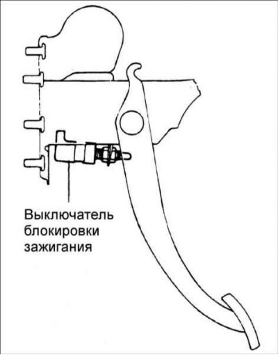
Check that the installation height, play and clearance of the clutch pedal socket pin are within normal limits.
Checking the starter relay
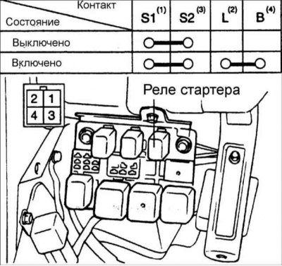
Remove the starter relay and check continuity between its terminals. If the conductivity is not as required, replace the relay.
Checking the ignition lock switch
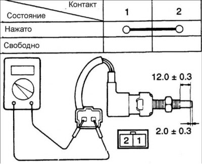
Check for continuity between the ignition interlock switch terminals.