
The pressure reducing valve, which is located at the outlet of the oil pump, opens when the oil pressure exceeds 5.6 bar, and part of the oil goes back into the oil sump.
The oil enters the main circuit along the central axis of the filter cartridge. There is an oil pressure switch that shows the driver a decrease in oil pressure by lighting up a control pump on the dashboard. The control lamp lights up when the oil pressure drops below 0.3 bar. Bypass valve allows unfiltered oil to pass into the main passage (clogged fuel filter).
Lubrication channels for crankshaft bearings depart from the main channel. Oil enters the connecting rod bearings through inclined holes, at the same time it rises through an inclined channel into the cylinder head, lubricating the camshaft bearings, rocker arms, and valve stems there.
The oil pump is made together with the crankshaft oil seal on the timing belt side of the engine. The inner rotor of the oil pump is connected to the crankshaft.
Some models also have an oil cooler. In this case, part of the oil after the oil pump goes to the oil cooler, which serves to improve the cooling of the oil and the engine.
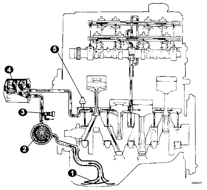
Oil circuit diagram
1 - oil receiver grid;
2 - oil pump;
3 - pressure reducing valve;
4 - oil filter;
5 - oil pressure sensor.