


Convergence
Toe-in is the position of the front wheels when the distance between the side surfaces of the tires at the front is less than at the rear, while reverse toe-in is when this distance at the rear is less than at the front. The purpose of adjusting the toe is to ensure that the wheels rotate parallel.
Wheel alignment is used to compensate for small deviations that may occur in the wheel suspension system as the vehicle moves forward. The set wheel toe angle is a preliminary adjustment that allows the toe value to be zero when the vehicle is in motion. Incorrect wheel alignment or toe-in will cause premature tire wear and prevent maximum fuel economy. As the vehicle's mileage increases, individual components of the steering and suspension system wear, and additional wheel alignment may be required to compensate.
Adjusting the toe-in value
The amount of wheel toe-in is adjusted by changing the length of the steering rods. Loosen the right and left tie rod nuts, then turn the tie rod ends to change the tie rod length to meet specifications.
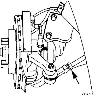
With this adjustment, the right and left steering rods should be the same length.
Tighten and lock the rods with locknuts.
Longitudinal angle of inclination of wheels
Roll is the forward or backward deviation from the vertical line when looking at the vehicle from the side. The tilt back is called positive (+), the tilt forward is called negative (-). The tilt of the steering axis affects the road holding, but does not affect the rate of wear of the tires. The amount of tilt can be affected by weak springs and vehicle overload.
If one wheel has more positive caster than the other wheel, this will cause that wheel to "pull" towards the center of the car. As a result, the car will pull towards the wheel with the less positive tilt. The tilt angle of the pivot axis is measured in degrees and is not adjustable.
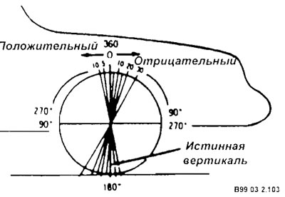
Wheel alignment
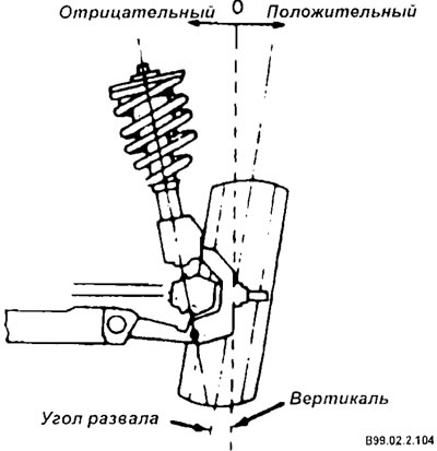
Camber is the deviation of the top of the tire from vertical when viewed from the side of the vehicle. When the top of the tire is tilted outward from the vertical, it is called positive camber (+). When the tire is tilted inward, it is called negative camber (-). Camber is measured in degrees from the vertical and is characterized by the camber angle. The camber angle affects both the road holding characteristics and the wear of the tires. If the vehicle has too much positive camber, the outside shoulder of the tire will wear. Likewise, if the amount of negative camber is too great, the inner shoulder of the tire will wear out.
The article is copied from this website hyundaibook
Tilt, like camber, is measured in degrees and is not adjustable.
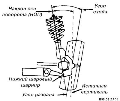
Pivot axis tilt (PATI) is the deviation (at the top) steering knuckle from the vertical. The NOP angle is measured between true vertical and a line passing through the center of the strut and lower ball joint when viewing the vehicle from the side. The steering axis tilt helps the vehicle maintain straight-line tracking and helps return the wheel to the straight-ahead position. The value of the NOP for vehicles with front drive wheels should be negative.
The tilt angle of the pivot axis is not adjustable.
Recommendations for checking wheel alignment angles
Complaints about steering problems and vibration are not always the result of improper wheel installation. They can also be caused by unbalanced wheels or tires. Another point that needs to be checked is that the tire may be "driving" due to a defect or severe wear. "Drift" is a deviation from straight-line movement on a level section of the road when there is no pressure of the hand on the steering wheel. To ensure correct wheel installation, before you begin measuring wheel alignment angles, you must check:
- air pressure in all tires (must comply with the norm);
- tread wear;
- clearance in wheel hub bearings;
- condition of ball joints (absence of play in them);
- tie rod ends (correct any detected deviations before adjusting the wheel angles);
- tire and wheel beating;
- condition of the rack and pinion in the steering system;
- proper functioning of the racks;
- condition of front suspension arms;
- possible overloading of the vehicle. If this excessive load is carried by the vehicle on a regular basis, check the installation angles under this load;
- reliability of the equipment used in checking and setting angles. Follow the equipment manufacturer's instructions strictly;
- regardless of the type of equipment used, the vehicle must be installed on a site that is level both longitudinally and transversely.
Note: Satisfactory vehicle operation can be achieved over a wide range of adjustments to the front suspension.
If the stated requirements cannot be met and the calculated technical characteristics cannot be obtained, check the vehicle for faulty suspension components. Make any necessary repairs or replacements.
If the adjustment fails to achieve the toe-in value within the established limits, the adjustment should be repeated
To obtain the correct values of the installation angles for the front wheels, the following conditions must be met:
- the tread pattern on all tires should be uniform and the tires themselves should be in good condition;
- the air pressure in the tires must be correct;
- all rims must be checked and in satisfactory condition;
- each front seat must be loaded with 70 kg;
- the fuel tank should be half full;
- rock the car a few times to stabilize the springs (also stabilize the springs if the car was previously lifted);
- when using installation equipment whose turntable does not capture lateral forces, the vehicle must first be rolled back one meter and then returned to its original position.
Wheel alignment methods vary depending on the equipment used. It is necessary to follow the instructions developed by the equipment manufacturer.