


Fuel vapor recovery system diagram
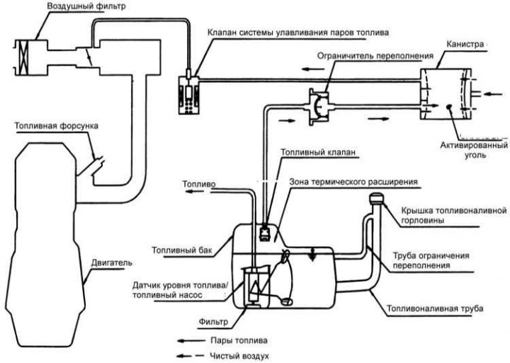
The fuel vapor recovery system prevents fuel vapor from evaporating into the atmosphere from the fuel tank, thereby preventing the formation of photochemical smog.
Fuel vapors are accumulated in a canister with activated carbon. When the engine is running, the electronic control unit opens the valve and fuel vapors enter the engine, where they are burned.
The control valve is used to control the fuel vapor pressure in the fuel tank.
Examination
1. Disconnect the vacuum hose from the throttle body and connect a vacuum pump with a vacuum hose in its place.
2. Check the following parameters with the engine cold and the coolant temperature below 60°C and with the engine hot and the coolant temperature above 80°C.
Cold engine
| Engine operating mode | Underpressure | Result |
| Idling | 50 kPa | Vacuum is maintained |
| 3000min⁻¹ |
Hot engine
| Engine operating mode | Underpressure | Result |
| Idling | 50 kPa | Vacuum is maintained |
| Within 3 minutes after increasing the rotation speed to 3000 min⁻¹ | Attempt to change vacuum | There is no vacuum |
| After 3 minutes of increasing the rotation speed to 3000 min⁻¹ | 50 kPa | The vacuum is maintained for a short time, after which it disappears |