
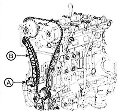
2. Install the crankshaft timing chain sprocket (B).
3. Install the chain oil nozzle (A).
Note: Tightening torque: 7.8-9.8 Nm.
4. Install the crankshaft so that the key is flush with the mating surface of the main bearing cap. Position the intake and exhaust camshafts so that the top dead center (TDC) marks on the sprockets are flush with the top surface of the cylinder head. This will place the No.1 cylinder piston at top dead center (TDC), compression stroke.
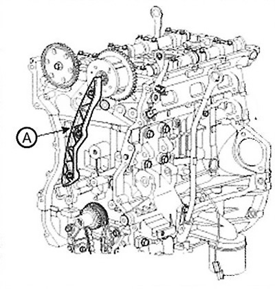
5. Install the timing chain guide (A).
Note: Tightening torque: 9.8-11.8 Nm.
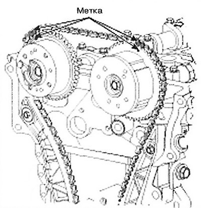
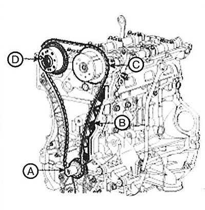
6. Install the timing chain.
To install the chain without slack between each shaft (camshaft and crankshaft), follow the order shown: Crankshaft sprocket (A) -> Timing chain guide (B) -> Intake camshaft sprocket (C) -> Exhaust camshaft sprocket (D): The marks on each sprocket must align with the timing chain marks (colored) when installing the chain.
 |
 |
7. Install the chain tensioner lever (B).
Note: Tightening torque: 9.8-11.8 Nm.
8. Install the automatic chain tensioner (A) and remove the installed stud.
Note: Tightening torque: 9.8-11.8 Nm.
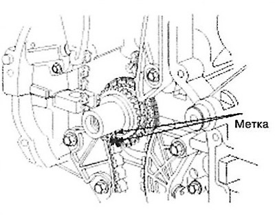
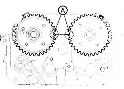
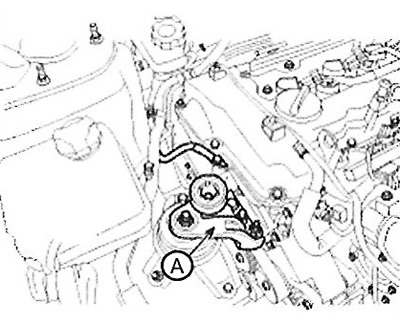
9. After turning the crankshaft 2 turns clockwise (front view), align the marks (A) as shown in the figure.
10. Install the timing chain cover.
Using a scraper, remove the old sealant from the surface under the gasket.
The areas where the sealant is applied to the chain cover, cylinder head, cylinder block and frame with cross members must not come into contact with oil, etc.
Before assembling the chain cover, Loctite 5900H or THREEBOND 1217H liquid sealant should be applied between the head and cylinder block.
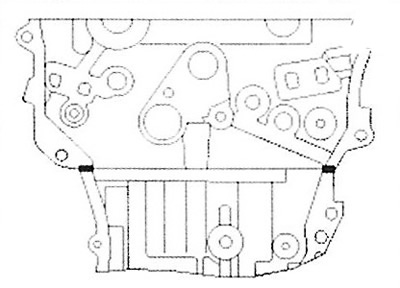
The parts must be assembled within 5 minutes after applying the sealant.
Note: Band width: 2.0L: 2.5mm. 2.4L: 3mm.
Install the timing chain cover.
Note: Tightening torque:
- 6x25: 7.8-9.8 Nm.
- 8x28: 18.6 - 22.5 Nm.
- 10x45: 39.2 - 44.1 Nm.
- 10x40: 39.2 - 44.1 Nm.
Firing and/or blowing of the timing chain cover must be carried out no later than 30 minutes after assembly.
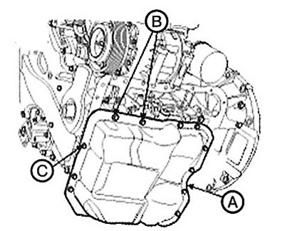
11. Install the oil pan.
Using a scraper, remove the old sealant from the surface under the gasket.
Before installing the oil pan, Loctite 5900H or THREEBOND 1217H liquid sealant should be applied between the cylinder block and pan joint surfaces.
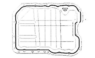
Attention.
- When applying sealant, do not allow sealant to enter the oil pan.
- To prevent oil leakage, apply sealant inside the mounting bolt holes.
Install the oil pan (A).
Screw bolts into several holes.
Note: Tightening torque: M6 (C): 9.8- 11.8 Nm. M9 (B): 30.4 - 34.3 Nm.
After assembly, wait at least 30 minutes before adding oil to the engine.
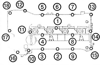
12. Install the cylinder head cover.
Any excess sealant squeezed out on the top surface of the chain cover and cylinder head must be removed before installing the cylinder head cover.
After applying the sealant (Loctite 5900H), assembly must be completed within 5 minutes.
Note: Strip width: 2.5mm.
Firing and/or blowing of the cylinder head must be carried out no later than 30 minutes after assembly.
Tighten the cylinder head cover bolts as follows: Step 1: Tightening torque: 3.9-5.9 Nm, Step 2: Tightening torque: 7.8 - 9.8 Nm.
Caution: Do not reuse the cylinder head gasket.
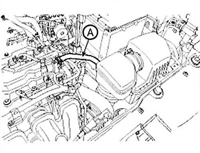
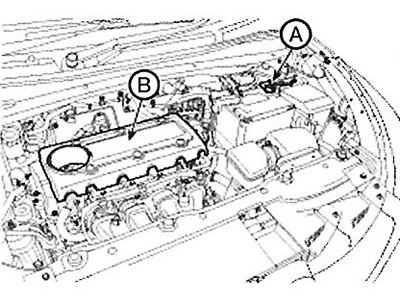
13. Install the breather hose (A).
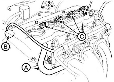
14. Connect the crankcase ventilation hose (A) and the oil flow control valve connector (B) to the outlet valves.
15. Install the ignition coils and connect the connectors (C) to them.
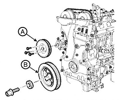
16. Install the crankshaft pulley (B).
Note:
- Tightening torque: 166.6 - 176.4 Nm.
- Use flywheel locking tool 09231-2B100 to install the crankshaft pulley bolt.
17. Install the water pump pulley
Note: Tightening torque: 7.8-9.8 Nm
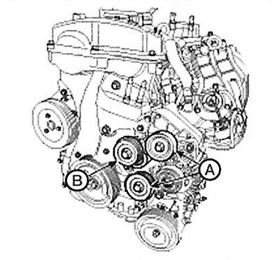
18. Install the drive belt tensioner (B).
Note: Tightening torque: 53.9 -63.7 Nm.
Caution: The tensioner pulley bolt has a left-hand thread.
19. Install the pulley (A).
Note: Tightening torque: 53.9 - 63.7 Nm.
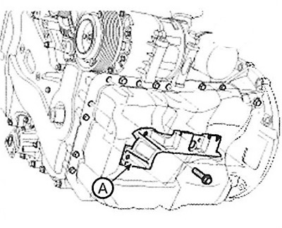
20. Install the air conditioning compressor bracket (A).
Note: Tightening torque: 19.6 - 23.5 Nm.
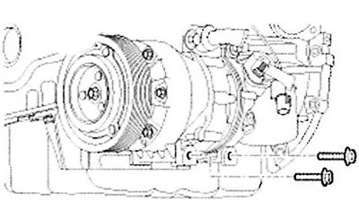
21. Screw in the lower air conditioning compressor mounting bolts.
Note: Tightening torque: 20.0 - 32.9 Nm.
22. Install the power steering pump to the bracket.
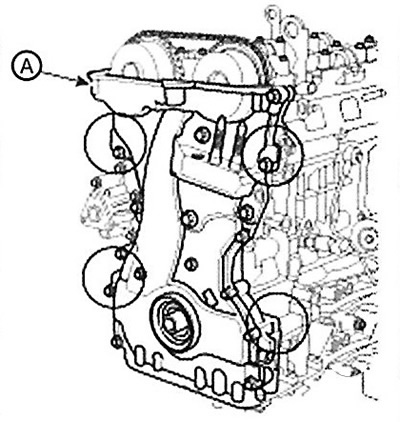
23. Install the drive belt (A) in the following order:
Crankshaft pulley -> air conditioner compressor pulley -> generator pulley -> intermediate pulley -> power steering pump pulley -> intermediate pulley -> water pump pulley -> tensioner pulley.
Rotate the automatic tensioner lever counterclockwise while moving the tensioner bolt with a wrench.
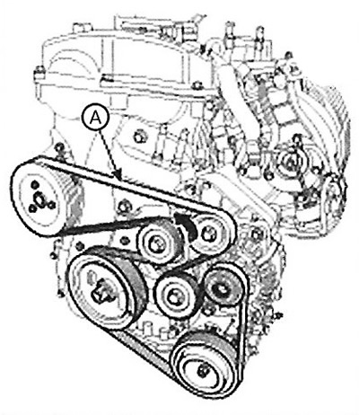
MDPS
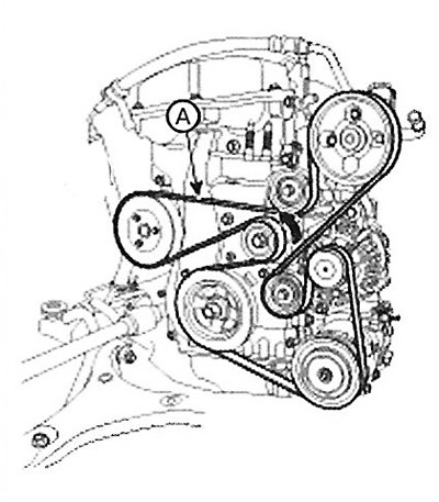
HPS
24. Install the engine mounting bracket (A) and connect the ground wire.
Note: Tightening torque: 63.7 - 83.4 Nm.
25.Install the side cover.
Note: Tightening torque: 8.8 - 10.8 Nm.
26. Install the front right wheel.
Note: Tightening torque: 88.3 - 107.9 Nm.
27. Install the engine cover (B).
28. Connect the negative cable (A) to the battery.
Note:
- Fill with engine oil.
- Before connecting the wires, clean their terminals and terminals
- battery with sandpaper. To prevent corrosion, coat the attached clamps with grease.
- Check for fuel leaks.
- After installing the fuel line, turn the ignition switch to the ON position (do not turn on the starter) so that the fuel pump can operate for approximately 2 seconds and pressure is built up in the fuel line.
- Repeat this operation 2-3 times and check the entire fuel line for leaks.
- Fill the radiator and its reservoir with coolant.
- Bleed the cooling system.
- Start the engine and warm it up (until the radiator fan comes on 3-4 times).
- Stop the engine and let it cool down. Check the coolant level and top up if necessary. This will remove air from the cooling system.
- Replace the radiator cap securely, start the engine again and check for leaks.